- Research Article
- Open access
- Published:
An Interference-Aware Admission Control Design for Wireless Mesh Networks
EURASIP Journal on Wireless Communications and Networking volume 2010, Article number: 106520 (2010)
Abstract
In this paper, we present IAC, an interference aware admission control algorithm for use in wireless mesh networks. The core concept of IAC is to use a low overhead dual threshold based approach to share the bandwidth information with its neighbors in the interfering range. As a result, IAC guarantees that the shared wireless bandwidth is not overutilized and the quality of all existing flows are preserved. Moreover, IAC takes into account the intraflow interference effect to estimate the bandwidth consumption of the flow in a multihop path. We have further proposed two approaches of bandwidth allocation, FCFS and MCU, and demonstrated that proper tuning of thresholds can lead to high performance of both schemes. Simulation results illustrate that IAC effectively limits the overutilization of channel resources which in turn results in high throughput, low delay and low packet loss rate for all admitted flows.
1. Introduction
Recent advances in wireless network communications have lead to the development of Wireless Mesh Networks (WMNs) [1–3], a promising technology that has the potential to provide wireless services in locations where there is currently little or no infrastructure. In WMNs, a collection of wireless mesh routers, usually employing IEEE 802.11-based commodity hardware operating in ad hoc mode, provides network access to the wireless clients. However, communications between mesh routers are realized by radio transmissions usually in a multihop fashion. One or more mesh routers in the network are connected to the Internet and serve as gateways to provide Internet connectivity for the entire mesh network. The existence of a wireless backhaul provides many advantages for mesh networks like market coverage, scalability, and low upfront cost.
As WMNs grow in popularity with numerous public and private deployments [4–6], the demand for multimedia services, such as Voice over IP (VoIP), Video on Demand (VoD), and interactive gaming, along with traditional data services is also increasing rapidly. These real-time services have stringent Quality of Service (QoS) requirements (e.g., low packet loss ratio and delay) for effective communication as compared to best-effort services that are tolerant to changes in bandwidth and delay [7–11]. In spite of the multiple advantages, it is fairly difficult to maintain a desired level of QoS for multimedia applications in a multihop network like WMN. This is attributed to many factors [1–3]: (a) unlike wired networks, the devices in mesh networks communicate via radio transmissions and hence, packet losses can occur due to error prone nature of wireless channel; (b) the interference among concurrent wireless transmissions either on a multihop path (intraflow interference) or on multiple paths in proximity (inter-flow interference) have an adverse impact on the performance of real-time flows. We have demonstrated the results of this impact using simulations in Section 2. Therefore, while designing algorithms for wireless mesh networks, one should take into account both the intraflow and the inter-flow interference among wireless links.
The current modus operandi of QoS provisioning in wired networks is not directly applicable to WMNs because of the differing nature of wired and wireless networks. Since WMNs share common characteristics with the ad hoc networks, the QoS solutions designed for ad hoc networks can be applied to WMNs. Nevertheless, the static nature of mesh routers and the mobile nature of client nodes implies that the solutions for ad hoc networks may not be suitable for WMNs. More specifically, new solutions incorporating special characteristics of WMNs need to be developed.
Generally, wireless networks have limited bandwidth resources and due to the shared nature of the wireless medium, communication from one node may use the bandwidth resources of the neighboring nodes which in turn leads to overutilization of resources [12–14]. Therefore, it is critical to employ admission control for the provisioning of QoS guaranteed services in wireless networks because it can avoid the system resources from being overused. In this paper, we propose an admission control algorithm known as Interference-Aware Admission Control (IAC) for single channel wireless mesh networks. IAC takes into account both the intraflow and inter-flow interference effect to make admission decisions. Therefore, a new flow is admitted only if there is enough local and neighboring bandwidth resources to support the flow. Thereby, IAC ensures that the shared resources are not overused and preserves the QoS of all admitted flows. The main contributions of this paper are given as follows.
-
(i)
We propose a dynamic, distributed admission control algorithm which adapts to the traffic conditions and takes into consideration the available bandwidth information of interfering neighbors in making admission decisions.
-
(ii)
We present a threshold-based scheme known as dual-threshold to mitigate the overhead caused by the bandwidth information exchanges while guaranteeing a desired level of QoS for all admitted flows in the network. The scheme also ensures that the channel resources are efficiently utilized. We call this optimized version of IAC algorithm as IAC/O.
-
(iii)
We propose two novel approaches for available bandwidth allocation and ensure that the shared wireless bandwidth is not overutilized and the quality of all existing flows are preserved.
The remainder of the paper is organized as follows: in Section 2, we discuss the motivations behind our work by stressing the necessity of a minimum overhead admission control in multihop networks. In Section 3, we discuss the related work for admission control in wired and wireless networks. Section 4 addresses the design of the proposed admission control algorithm in detail. In Section 5, we discuss the implementation of the proposed algorithm in the context of AODV routing protocol [15]. In Section 6, we present an analysis of the deterministic and adaptive dual-threshold scheme. Simulation results and their analysis are discussed in Section 7. In Section 8, we present the discussions and future enhancements. Finally, Section 9 concludes this paper.
2. Example and Motivation
In mesh networks, due to the shared nature of the wireless medium, nodes compete for channel bandwidth not only with the neighbors in their communication range but also with the nodes in their carrier sensing range. As a result, the shared channel bandwidth can be easily overutilized which in turn affects the quality of the existing flows. To capture the available bandwidth of the wireless network accurately [12], we need to consider two types of bandwidth: local available bandwidth and neighbor available bandwidth. Local available bandwidth is the amount of spare bandwidth observed by the given node whereas neighbor available bandwidth is the amount of spare bandwidth that a given node can consume without affecting the quality of the existing flows in its transmission and carrier sensing range. Therefore, the amount of bandwidth available for a given node is the minimum of the local available bandwidth and neighbor available bandwidth. To further illustrate the importance of the local and neighbor available bandwidth in wireless networks, we show a simple simulation using Ns2(v2.29) [16] as follows.
2.1. Example
As shown in Figure 1, we used a grid topology of 16 mesh nodes. The MAC layer protocol is IEEE 802.11 CSMA/CA with 250 m radio transmission range and 550 m carrier sensing range. The bandwidth of the wireless channel is set to 2 Mb/s. Three CBR flows (1, 2, 3) of 545 Kb/s are established between nodes 2 and 3, nodes 6 and 7, and nodes 14 and 15, respectively. Nodes 2 and 14 are the direct and carrier sensing neighbors of node 6 whereas nodes 2 and 14 are out of the contention range. Each flow requires about 46.5% of the channel bandwidth due to the MAC layer (RTS/CTS/DATA/ACK handshake) overhead [13, 17]. At time  second, node 2 initiates flow 1 to node 3. At
  seconds, node 6 initiates flow 2 to node 7. Finally, at time
  seconds, node 14 initiates flow 3 to node 15. Figures 2 and 3 shows, respectively, the throughput and delay of each flow over time. The results of the performance evaluation can be explained as follows: nodes 2 and 6 are direct neighbors and hence, after flow 1 starts, the local available bandwidth at these nodes is reduced to 53.5% of channel bandwidth. Since node 6 is a direct and carrier sensing neighbor of nodes 2 and 14, initiation of flow 2 consumes the bandwidth of nodes 2, 6, and 14. This reduces the local available bandwidth for these nodes to 7%, 7%, and 53.5% of channel bandwidth, respectively. At time
  seconds, node 14 admits the flow 3 for any one of the following reasons: (a) an admission control protocol is not employed; (b) an admission control protocol is employed. However it only considers the local available bandwidth (53.5% of channel bandwidth) and not the neighbor available bandwidth (7% of channel bandwidth). What will happen if node 14 admits the flow
  ? The local available bandwidth of node 6 (7%) is much less than the consumption of flow 3 (46.5%). Therefore, when node 14 starts flow 3, the contention from it actually decreases the throughput of flow 2 by 8% (see Figure 2) and increases the delay of flow 2 from 0.05 s to 0.45 s (see Figure 3). Since the real-time flows have stringent QoS requirements (for e.g., the delay for an acceptable VoIP flow should be less than 200 ms according to the ETSI recommendation [7–9] and the loss rate should be no more than 1%), it is easy to conclude that the increased delay (0.05 s to 0.45 s) and reduced throughput of flow 2 will have an adverse impact on the perceived quality of the flow.

 Grid simulation topology. three flows, 1: (2-3), 2: (6-7), 3: (14-15), are established.

Throughput of three flows (1, 2, 3) versus time. RTS/CTS mechanism is enabled.

Delay of three flows (1, 2, 3) versus time. RTS/CTS mechanism is enabled.
2.2. Motivation
To preserve the quality of existing flows in a multihop network like WMN, one should take into account two kinds of interference: intraflow interference and inter-flow interference. (Inter-flow interference is the interference caused when the nodes on the adjacent path contend with each other for the channel bandwidth (for e.g., flows 2 and 3 in Figure 1), whereas intraflow interference is the interference caused when the nodes on the path of the same flow contend with each other for the channel bandwidth.) Though our work is closely related to [12], the major difference of the proposed algorithm, IAC, stems from mitigating the overhead caused by the bandwidth information exchanges seen in CACP [12], MARIA [18] while guaranteeing a desired level of QoS for all admitted flows in the network. The issue is so important because the exchanges of information proposed in [12] or [18] may cause high overhead in the network and in turn consume a part of the bandwidth available for data transmission. To achieve the objective of reducing overhead, we propose novel dual-threshold scheme and event-driven message exchange to share the bandwidth information in the neighborhood, which indeed is the motivation behind this work.
3. Related Work
In this section, we discuss several existing admission control algorithms in the area of wired, ad hoc, and wireless mesh networks. Traditional approaches like IntServ/RSVP and DiffServ [11] for QoS provisioning on the internet do not work well for wireless networks due to the inherent distinctions between the wired and wireless networks. For example, these approaches fail to address the challenges involved in estimating the available bandwidth required by the flow in a shared wireless medium. INSIGNIA [19] and SWAN [20] are both protocols that provide QoS guarantees by controlling the traffic in ad hoc network. INSIGNIA relies on in-band signaling by piggybacking the control information on data. This in-band signaling allows INSIGNIA to quickly reestablish flow state when topology changes occur. SWAN, an alternative to INSIGNIA, is characterized by its improved scalability. Here, the per-flow information is not stored in the intermediate nodes and therefore the protocol avoids complex signaling which makes the system more simple and scalable. However, the downside of both these schemes is that neither takes into account the fact that the communication from one node may consume the resources of the neighboring nodes in addition to its local resources.
TAC [21] and AAC-AODV [22] implement flow admission control based on intraflow interference. However, both these schemes do not give enough attention to inter-flow interference and thus, fail to estimate the neighbor available bandwidth. In [23, 24], the authors rely on interference-capacity model to design an admission control algorithm for VOIP calls in mesh network. The algorithm performs admission control by monitoring the number of calls and determines whether the maximum capacity is reached. When the call limit reaches the maximum, the admission controller will reject further call requests. However, the approach fails to consider the load in the network. Since the degree of interference caused by each node depends on the traffic carried by the flow, merely monitoring the calls can fail to accurately model the interference and can lead to erroneous admission decisions. Additionally, the authors use the interference-capacity model obtained from a chain topology to achieve call admission control in generic random topology. However, such approximation schemes cannot accurately model the inter-flow and intraflow interference in a mesh network and thus can lead to admission of calls beyond the network capacity. In [25], authors propose an admission control algorithm for multiconstrained, multilevel QoS routing in wireless mesh networks. Their design employs two phases, the QoS performance index estimation phase, and multilevel QoS and GoS resource management phase to efficiently manage the resources among existing and new flows.
In MARIA [18], the authors characterize interference in wireless mesh networks using the well-known conflict graph based model. In this approach, the nodes exchange their flow information periodically using high power HELLO messages to determine their remaining available bandwidth based on the maximum clique constraints. The main drawback of MARIA is that these periodic exchanges of information using extended power cause high overhead in the network and in turn consume a part of the bandwidth available for data transmission. CACP [12] addresses admission control for ad hoc networks and factors both the effect of intraflow and inter-flow interference. Nonetheless, CACP has the following drawbacks: (a) CACP supports only source routing protocols like DSR [26]; (b) CACP determines the available bandwidth of all the nodes within the transmission and carrier sensing range by sending a query message to these nodes. If any node that receives the query does not have enough resources to support the flow, it sends a rejection message. This query process is performed on a hop-by-hop basis during the route discovery phase. However, this process is time consuming and imposes a high message overhead in the network which in turn consumes a part of the bandwidth available for data packet delivery [14]. PAC [14] performs admission control by relying on a passive approach to determine the available bandwidth at the interfering neighbors. Although, this approach has lower overhead, the process of estimating available bandwidth is conservative. Additionally, PAC does not give enough attention to intraflow interference. As opposed to these approaches, in [27], authors present a statistical connection admission control framework to estimate the network resource for a pair of ingress-egress nodes and make admission decision based on this estimated result. Their approach ensures a low signalling overhead-based admission control algorithm for wireless networks.
Some other notable works in the area of admission control algorithm in multihop networks are [28–31]. In the area of admission control algorithms for multichannel wireless networks [28, 30], for instance authors in [28] propose a QoS routing for multiradio multichannel IEEE 802.11 wireless mesh networks. To enhance the throughput, they further present a new routing metric to select the most efficient route among all feasible ones. In [29], authors explore the problem of admission control and scheduling of flows in multi-hop WiMAX networks. In particular, they propose efficient heuristic algorithms for scheduling flows in a centrally scheduled multi-hop WiMAX network. Finally, in [31] authors propose an integrated admission control and routing mechanism for multirate wireless mesh networks. They discuss a DCSPT method for available bandwidth estimation, based on dual carrier sensing with parallel transmission awareness and introduce a packet probing-based available bandwidth estimation method, suitable for legacy device implementations. These techniques are further integrated in an admission control mechanism designed for a hop-by-hop routing protocol (LUNAR), enabling alternate route identification when shortest paths are congested.
4. Design of Interference-Aware Admission Control Algorithm (IAC)
As emphasized before, the main objective of IAC is to mitigate the overhead involved in estimating available bandwidth information at each interfering neighbor seen in existing literatures such as CACP [12], MARIA [18]. For this purpose, IAC requires each node locally to estimate the channel utilization ratio and then to compare with the threshold to determine whether the current channel utilization has exceeded the minimum permissible threshold. If exceeded, each node is required to compute the available bandwidth and broadcast this information to all the interfering nodes. IAC requires all the receiving nodes to buffer these broadcasts and as a result, when a new flow request arrives at each node, it locally determines whether the incoming flow can be accepted by comparing the new flow requirement with the buffered bandwidth information.
In this sequel, initially we discuss how to determine the local and neighbor available bandwidth of a given node. Then, we focus on the design of the proposed algorithm, IAC and several challenges associated with the design of IAC.
4.1. Estimation of Local Available Bandwidth
As mentioned in Section 2, the local available bandwidth is defined as the unused or spare bandwidth observed by a given node. The most common way to measure the available bandwidth ( ) is to determine the channel utilization (
 ). Given
  , the total channel bandwidth, and
  , the channel utilization, the available bandwidth (
 ) is defined as [32]

Many techniques have been proposed for measuring the channel utilization as given in [12, 14, 33]. In this paper, we use the fraction of the busy time during every time period  as an indication of the channel utilization at a node. A node can easily detect the state of the channel as idle or busy by monitoring the network activities since the IEEE 802.11 is a CSMA-based MAC protocol, working on the virtual and physical carrier sensing mechanisms. The wireless medium around a node (the channel) is determined to be busy due to any of the following reasons: (a) transmitting or receiving the packets by the node; (b) sensing a signal with strength greater than carrier-sense threshold. Nonetheless, the node cannot decode the contents of the message if it is within the carrier-sensing range and outside the transmission range of the sender; (c) the network allocation vector, (NAV), which indicates the channel is busy due to activity of other nodes [17].
We estimate the channel utilization,  , as a fraction of the time the channel is detected as busy due to transmission or reception of packets or sensing (virtual or physical carrier sensing) other packet transmissions. The channel utilization,
  , and the local available bandwidth
  are expressed as follows:

where  is the amount of busy channel time monitored by the node during every time period
  .
.
Figure 4 depicts the channel utilization observed by the nodes with respect to the simulation topology in Figure 1. It can be observed from the figure that at time  seconds, the channel utilization for node 6 is 92% and for node 14 is 46%. As a result, when node 14 admits the flow at time
  seconds, the channel utilization observed by node 6 reaches above 99% and therefore, QoS of flow 2 falls below the desired level. From this observation, we can conclude that channel utilization provides an accurate estimation of local available bandwidth,
  , at a given node.

Channel utilization (%) with respect to three flows (1, 2, 3) versus time. RTS/CTS mechanism is used.
4.2. Estimation of Neighbor Available Bandwidth
As discussed in Section 2, an admission control algorithm should take into consideration both the local available bandwidth and neighbor available bandwidth of a given node to maintain the quality of all admitted flows in the network. However, estimation of a node's own local available bandwidth cannot provide information about its neighbor available bandwidth or the local available bandwidth information of nodes in its transmission or carrier sensing range. For example, as mentioned in Section 2, at time  seconds, node 14 estimated its unused bandwidth as 53.5%. On the other hand, node 14 does not know the amount of bandwidth available at node 6 which is 7%. Therefore, the amount of bandwidth available for a given node (
 ) is the minimum of the local available bandwidth (
 ) and neighbor available bandwidth (
 ). Consequently, we propose an active technique to attain the local available bandwidth information of the nodes within the transmission and carrier sense range of a particular node. In active technique, nodes actively exchange their local available bandwidth information between each other. Since nodes cannot communicate directly with the nodes in their carrier sense range, such information exchange is done with high transmit power which in turn results in high overhead [12]. Nonetheless, these active techniques can provide accurate information about the local available bandwidth of the interfering neighbors. Therefore, to compensate for the overhead caused by the active technique, we propose an optimized version of the IAC algorithm known as Interference-Aware Admission Control Optimized (IAC/O) that uses a threshold based approach for the exchange of bandwidth related messages.
In IAC/O, each mesh node monitors the state of the surrounding wireless medium to measure the channel utilization. We denote the measured channel utilization as  . It is important to note that this process has little overhead since the IEEE 802.11 CSMA/CA protocol works on virtual and physical carrier sensing [13, 17]. During every time period
  , the node computes the fraction of busy channel time,
  , to determine the channel utilization,
  , where
  .
.
The IAC/O is a dual-threshold scheme relying on two thresholds  and
and  .
.  is the lower channel utilization threshold whereas
  is the upper channel utilization threshold. The following relationship exists between the thresholds and the maximum channel utilization,
  . We limit the maximum channel utilization of the network to
  to avoid congestion due to overutilization of the resources due to incorrect admissions. Therefore, when the channel utilization exceeds
  , the nodes in the interfering range set their available bandwidth to zero and reject new flow requests. (Note that, if IAC depend only on
  , then there is high probability for overutilization of the resources due to incorrect admissions of flows. Thus to avoid this situation, before reaching the maximum utilization IAC requires the nodes to give a notification message to its interfering neighors about their current channel utilization. To achieve this objective, IAC requires a minimum threshold,
  .)
.)
As depicted in Figure 5, given the two thresholds  and
and  , we divide the channel utilization into three ranges:
  (lower range),
  (medium range) and
  (higher range). Once the channel utilization
  , is determined, each node compares
  with the thresholds,
  and
and  , to determine the range. Based on the range in which
  lies, the node performs the following operations.
-
(i)
 (completely congested): in this range, the following relationship exists between the thresholds and the current channel utilization,
  . Assume that node
  's channel utilization exceeded the upper threshold
  , during time period
  . Since the channel utilization exceeded the upper threshold, node
  assigns the
  to zero and broadcasts an event message, bandwidth lost (bw_lost), to all the nodes in its transmission and carrier sensing range. When the interfering neighbors of node
  receive the bw_lost message, they decide their available bandwidth (
 ) as follows:
 (3)
(3)where
 is the set of interfering neighbors of node
  . Since the interfering nodes in
  do not have enough available bandwidth to admit a new flow, the channel will not be overused and accordingly, the quality of all admitted flows will be preserved.
 -
(ii)
 (moderately congested): in this range, the following relationship exists between the thresholds and the current channel utilization,
  . Suppose that during time period
  , node
  's
's  exceeded the lower threshold,
  . When this occurs, node
  computes its available bandwidth,
  , as follows:
 (4)
(4)and broadcasts an event message, bandwidth critical (bw_critical), to all the nodes in its transmission and carrier sensing range (i.e. interfering neighbors). When the interfering neighbors of node
 receive the bw_critical message, they record the local available bandwidth information of node
  and determines their available bandwidth as follows:
 (5)
(5)where
 and
and  are the set of interfering neighbors of nodes
  and
and  , respectively.
  is the neighbor available bandwidth of all interfering nodes of
  obtained via bw_critical or bw_lost message.
Figure 5 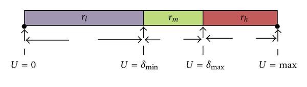
Channel utilization ranges defined on the basis of thresholds,
 and
and  . When
  , the nodes are moderately congested, whereas when
  , the nodes are completely congested.
 (completely congested): in this range, the following relationship exists between the thresholds and the current channel utilization,
  . Assume that node
  's channel utilization exceeded the upper threshold
  , during time period
  . Since the channel utilization exceeded the upper threshold, node
  assigns the
  to zero and broadcasts an event message, bandwidth lost (bw_lost), to all the nodes in its transmission and carrier sensing range. When the interfering neighbors of node
  receive the bw_lost message, they decide their available bandwidth (
 ) as follows:
 is the set of interfering neighbors of node
  . Since the interfering nodes in
  do not have enough available bandwidth to admit a new flow, the channel will not be overused and accordingly, the quality of all admitted flows will be preserved.
 (moderately congested): in this range, the following relationship exists between the thresholds and the current channel utilization,
  . Suppose that during time period
  , node
  's
's  exceeded the lower threshold,
  . When this occurs, node
  computes its available bandwidth,
  , as follows:
 receive the bw_critical message, they record the local available bandwidth information of node
  and determines their available bandwidth as follows:
 and
and  are the set of interfering neighbors of nodes
  and
and  , respectively.
  is the neighbor available bandwidth of all interfering nodes of
  obtained via bw_critical or bw_lost message.
 and
and  . When
  , the nodes are moderately congested, whereas when
  , the nodes are completely congested.
In order to make accurate decisions in this range, we require the moderately congested nodes to exchange information about the available bandwidth with their interfering nodes. This information exchange can be either periodic exchange or event-driven exchange. In the periodic exchange, the bw_critical message is sent to the interfering neighbors every  second provided that the current channel utilization is within range
  . This approach has high overhead and therefore to compensate for the overhead involved in periodic message exchange, we employ the second approach of information exchange known as event-driven. In this approach, whenever the channel utilization changes to a new value within the range
  , a bw_critical message is sent to the interfering neighbors. This scheme is accurate and has lower overhead. Our simulation results also demonstrate that event-driven exchange performs better when compared to periodic exchange.
-
(i)
 (uncongested): In this range, the following relationship exists between the thresholds and the current channel utilization,
  . Since the channel utilization is below the lower threshold, the nodes do not exchange any bandwidth related information with their interfering neighbors to reduce the overhead.
In addition to the two event messages (bw_critical and bw_lost), we employ a third message known as bandwidth recover (bw_recover). Assume that the channel utilization,  , exceeded
  or
or  during time period
  . In the next time period, if
  falls below the lower threshold by
  (i.e.,
  ) a bw_recover message is transmitted to the interfering neighbors. As a result, bw_recover message prevents the system resources from being underutilized. The threshold
  is used to reduce the overhead associated with the value of
  oscillating between the ranges. A smaller
  provides efficient channel utilization at the expense of overhead. On the other hand, a larger
  incurs low overhead but may result in under-utilization of channel resources. Therefore, while designing
  , we need to carefully maintain a tradeoff between overhead and channel utilization.
It is important to note that the event messages are exchanged only when the channel utilization exceeds the threshold  and hence, IAC/O has less overhead compared to the active techniques discussed in [12]. Algorithm 1 summarizes the estimation of neighbor available bandwidth.
Algorithm 1
# Initialize State to true.
State= true;
if  then
then
if (State= true) then
do nothing;
else
# State is equal to false
if  then
then
State= true;
send_bw_recover();
end if
end if
else
if  and
and  then
then
State= false;
 ;
;
send_bw_critical ;
;
else
if  and
and  then
then
State= false;
 ;
;
send_bw_lost ;
;
end if
end if
end if
IAC/O: Estimation of 
In the following sections, we present several challenges encountered while implementing IAC/O algorithm and discuss solutions for each.
4.3. Model for Neighbor Communication
In a CSMA-based MAC protocol [13, 17], the carrier sensing range of wireless nodes is typically larger than their transmission range. Nodes that are outside the transmission range but within the carrier sensing range can sense packet transmissions; however, they are unable to interpret the contents of the packet. Therefore, direct communication is ineffective for sharing bandwidth information with such nodes.
Several methods for communicating with carrier sensing neighbors have been discussed in [12, 14]. In IAC/O, we employ the high transmit power approach presented in [12] for sharing bandwidth related information. This technique relies on a high transmission power to broadcast the bandwidth related event messages (bw_critical, bw_lost, bw_recover) to the nodes within the transmission and carrier sensing range. Using this high transmit power approach, all nodes within the interfering range of the sender node are contacted. It is not hard to deduce that these high power messages may incur high interference as opposed to data transmission with normal power. However, it is important to note that, this high transmit power approach does not induce much overhead in IAC/O due to the following reasons. (a) Event messages are exchanged only when the channel utilization exceeds the threshold. For example, when  exceeds
  , a bw_lost message is sent to the interfering nodes to inform them about the available bandwidth resources. Therefore, transmitting an event packet is an infrequent event as opposed to the data transmission. (b) Event messages are broadcast packets. Therefore, a single message from the sender node will reach all the nodes within the transmission and carrier sensing range of the sender.
4.4. Model for Available Bandwidth Allocation
As mentioned in Section 4.2, during every time period  , each node computes the current channel utilization
  and determines whether
  has exceeded the thresholds
  and
and  . If the channel utilization has exceeded the thresholds, the node computes the local available bandwidth and transmits the corresponding event messages with this information within its neighborhood using the mechanism described in Section 4.3. In this section, we discuss the issue of sharing the remaining bandwidth among the interfering neighbors of a given node so that the channel resources are efficiently utilized.
For example, consider the topology in Figure 6 and the channel utilization observed by node C in Figure 7. Figure 7(a) depicts the utilization of channel at time  , when no flows are admitted in the network. Suppose that at time
  , three flows are admitted by nodes A, B and C. Figure 7(b) depicts the current channel utilization observed by node C at time
  . However, after the initiation of three flows, the utilization
  exceeded the lower threshold
  . Consequently, node C computes the local available bandwidth using (4) and broadcasts the event message, bw_critical, to nodes within its neighborhood. When the interfering neighbors of node C (nodes A, B, and G) receive the bw_critical message, each node determines the available bandwidth as given by (5). How should nodes A, B, C, and G share the remaining bandwidth at node C so that the quality of all the admitted flows are preserved? It is important to note that we should take into account the issue of bandwidth sharing only when
  is in the range
  . When
  , the local available bandwidth is set as zero and hence, bandwidth sharing need not be considered.

A simple topology. Nodes A, B, and G are interfering neighbors of node C. Nodes A and G are the direct neighbors of node C; node B is the carrier sensing neighbor of node C.

Channel Utilization observed by node C during every time period T. The channel bandwidth  is reserved (
 ) to avoid channel overutilization.Channel Utilization at time (
 ,
,  )Channel Utilization at time (
 ,
,  ) after admitting flows by Node A, B, and CFCFS Allocation scheme at time (
 ,
,  ): Flow from Node G admittedUtilization-based Allocation sceme at time (
 ,
,  ): Flow from G not accepted.
As discussed in previous sections, since the interfering neighbors of a given node cannot communicate directly, the sharing of available bandwidth is NOT a straight forward process. Additionally, since the given node is unaware of the number of carrier sensing neighbors, a fair sharing of available bandwidth is not possible. In this section, we discuss two unfair bandwidth allocation schemes: First Come First Serve (FCFS) allocation and Maximum Channel Utilization-based (MCU) allocation.
We present each of the following allocation schemes with respect to the topology in Figure 6.
4.4.1. First Come First Serve (FCFS) Allocation
In this approach, any interfering neighbor of a given node can admit the flow if its available resources,  , satisfies the bandwidth requirement of the flow. As an example, suppose that at time
  , node G receives a new flow request and determines whether
  satisfies the bandwidth requirement of the new flow. If enough resources are available, node G will accept the new flow. Figure 7(c) shows the channel utilization observed by node C after the initiation of flow by node G. However, it is evident that there is no fixed pattern of sharing the available bandwidth between one or more flows. As discussed in previous sections, since the carrier sensing neighbors may not be able to communicate with each other, there is a high probability that one or more flows are initiated simultaneously which can cause starvation to the existing flows.
To compensate for this drawback of FCFS approach, IAC/O design employs  in dual-threshold scheme. We have discussed in Section 4.2 that IAC/O requires each node to limit the channel utilization to
  and the remaining channel bandwidth
  ) is reserved. Thus, even though one or more flows are admitted concurrently, tuning
  approximately can avoid channel overutilization.
4.4.2. Maximum Channel Utilization-Based Allocation (MCU)
In this approach, each node gets access to the remaining channel bandwidth based on the channel utilization history. In other words,
"The more the node utilizes the channel, the more the share of the remaining available bandwidth".
Figure 7(b) shows the state of the channel observed by node C after the initiation of flows from node A, B, and C. Hence, after the admission of flows from A, B and C, the available channel bandwidth is reduced to  . For example, consider that during next time period
  , each node (A, B, C, and G) receives a new flow request from its corresponding application layer. In this scenario, we need to determine how efficiently the remaining channel resources can be shared among nodes A, B, C, and G so that the channel is not overused.
Firstly, according to maximum channel utilization based allocation (MCU) scheme, node G will not receive a share of the remaining bandwidth since it has not utilized any fraction of the channel resources in previous time slots. As a result, node G rejects the new flow request.
Secondly, we have to determine how to allocate the remaining bandwidth resources among nodes A, B, and C. Since node C is unaware of the number of active carrier sensing neighbors, a fair share of bandwidth is not possible. However, each node is aware of the fraction of the bandwidth resources it used during the previous time period  . As an example, suppose that each flow from nodes A, B, and C used
  share of the total channel bandwidth
  . Each node computes the fraction of bandwidth consumption (
 ) as follows:

Once  is determined, each node individually calculates the remaining bandwidth share (
 ) that can be consumed without affecting the quality of existing flows. Suppose
  is the node that transmitted bw_critical message to its interfering range and the
  of each interfering node in this approach is expressed as follows:

where  is the set of interfering neighbors of node
  and
and  is the set of interfering neighbors of node
  . Figure 7(d) shows the MCU scheme.
The upside of the scheme is that: (a) the remaining bandwidth will not be subjected to an excessive amount of demand. Therefore, channel will never be overutilized; (b) nodes that always have data to send are never deprived of an opportunity to do so. However, the downside of the scheme is that heavily loaded nodes (nodes A, B, and C) may hog the remaining bandwidth and the new nodes (for, e.g., node G in Figure 6) are never given an opportunity to transmit.
It is important to note that the upside of both schemes rely on the difference between  and
and  . The smaller the difference, MCU-based allocation performs better because the remaining bandwidth can be efficiently utilized without subjecting to an excessive amount of demand. However, the larger the difference, FCFS-based allocation scheme performs better because of the following reasons: (i) all nodes get a chance to transmit as opposed to MCU based scheme; (ii) even though one or more flows are admitted simultaneously, the overutilization of channel can still be avoided.
5. Algorithm Implementation
In this section, we present the implementation of IAC/O algorithm in the context of the AODV [15] routing protocol. However, the concepts under discussion can be applied to other multihop routing protocols [26] as well. Our main contributions in this section are the following.
-
(i)
computation of bandwidth requirement of a flow.
-
(ii)
Estimation of intraflow interference.
-
(iii)
Implementation of IAC/O.
5.1. Computation of Bandwidth Requirement of a Flow ( )
)
 )
)In this section, we present the scheme for computation of the bandwidth requirement of a new flow so that the admitting node can determine whether its available bandwidth can support this new flow. Initially, the data rate of the application must be converted into the corresponding channel bandwidth requirement. In this process, the medium access control and network layer overhead should be taken into account. For IEEE 802.11 MAC using RTS/CTS/DATA/ACK handshake [13, 17], the transmission time of each data packet,  , can be determined as follows:

where, S is the size of the data packet including the MAC and IP header length,  and
and  represent the time for transmitting RTS, CTS, and ACK packets, respectively.
  and
and  denote the interframe spaces SIFS and DIFS, respectively.
  is the channel bandwidth.
If the application at the sending node generates N packets per second, then its corresponding bandwidth requirement ( ) can be expressed as follows:

5.2. Estimation of Intraflow Interference
In multihop networks, we should take into account the interference caused when the nodes on the path of same flow contend with each other for the channel bandwidth, known as intraflow interference [3]. To understand the significance of intraflow interference, consider the multihop path in Figure 8. Here all nodes are equally spaced at 250 m apart. The shaded area represents node A's carrier sensing range and the dashed circles represent each node's transmission range. In Figure 8, node B is the direct neighbor and node C is the carrier sensing neighbor of node A. Thus, nodes A, B and C cannot transmit a flow at the same time. Hence, the number of nodes that interfere with each node's transmission in a multihop path is called as contention count and denoted as  . In Figure 8, the contention count at node A is 2. Therefore, the bandwidth consumption of the flow,
  , at each node
  can be expressed as follows [12]:


Example  : A is the source and F is the destination. The carrier sensing range of node A is shown as shaded area. In this topology all nodes are equally spaced at 250 m apart.
Generally, the computation of contention count is not a straight forward process. Some of the earlier works [21, 22] computed  by taking into consideration that the carrier sensing range is approximately twice the size of the transmission range and hence, the number of two-hop neighbors on the path can be used to approximate
  . However, we show that this approximation can not be applied to all cases. For example, consider the topology shown in Figure 9. We modify the transmission distance between each node so that node A's carrier sensing range now includes nodes B, C, D and E. In this case, the contention count at node A is 4 which is clearly higher than the number of two-hop neighbors.

Example  : A is the source node and F is the destination node. The carrier sensing range of node A is shown as shaded area. Here, the transmission distance between the nodes AB, BC, CD, DE, and EF are modified as 60 m, 200 m, 60 m, 200 m, and 200 m, respectively.
Note: We do not include destination in the contention count computation, because the destination node only passively receives traffic and hence does not contribute to channel contention. For example, in Figure 9, the contention count at node C is only 4 (Nodes A, B, D, and E).
We can estimate  in a multihop environment, if some location information of nodes could be distributed in the network during route discovery phase. For example, each node may append its location information in the route discovery packets before forwarding them. Given the location information of each node in the packet,
  can be determined as given in Algorithm 2.
Algorithm 2: IAC/O: Estimation of  of each node.
#  contention count of each Node
  ;
;
#  set of nodes that marked the packet with location;
#  carrier sensing range;
#  ID of node
  ;
;
#  Distance between node
  and
and  ;
;

for all  do
do
if  &
& Destination then

else
do nothing;
end if
end for
The drawback of this approach is that the length of the message increases with the number of hops which in turn increases the packet transmission time. However, it is important to note that the route discovery process is initiated only when a node has data to send, which is a much rarer event as opposed to the data transmission itself.
5.3. Implementation of IAC/O
In previous sections, we discussed on estimating available bandwidth at each node by taking into account the effect of inter-flow and intraflow interference. In this section, we focus on setting up a bandwidth aware end-to-end route between a source and destination pair. In other words, the proposed approach ensures that each node on the selected path has enough available bandwidth to support the new flow from source node. We discuss the algorithm implementation in the context of AODV routing protocol.
5.3.1. Route Discovery in AODV
In AODV, when a source has data to send to an unknown destination, it broadcasts a Route Request (RREQ) for that destination [3, 15]. At each intermediate node, when a RREQ is received, a route to the source is created and stored. Each receiving node rebroadcasts the RREQ, if: (a) it has not received this RREQ before; (b) it is not the destination; (c) it does not have a current route to the destination. If the receiving node is the destination or has a fresh route to the destination, it generates a Route Reply (RREP). The RREP is unicast in a hop-by-hop fashion to the source. As the RREP propagates, each intermediate node also records the route to the destination. When the source receives the RREP, it records the route to the destination and can begin sending data. If multiple RREPs are received by the source node, the route with the smallest metric is chosen.
5.3.2. QoS-Aware Route Discovery
To facilitate QoS provisioning, we add the following fields to RREQ and RREP packets of the AODV protocol.
-
(i)
 : bandwidth requirement of the new flow as calculated by the source node.
 -
(ii)
Location_list: each node appends its location in the route discovery packets.
 : bandwidth requirement of the new flow as calculated by the source node.
When the source node receives a new flow request, it broadcasts the RREQ message. Besides the original fields in RREQ, the route request now also contains the bandwidth requirement of the new flow ( ) and the location of the source node. When each intermediate node receives the route request, it performs admission control by determining whether the node has enough resources (
 ) to support the new flow. Note that since the nodes do not have any information about the contention count, they compare the required bandwidth of the flow,
  , with the available resources,
  . If the bandwidth request is smaller than the available resources, the receiving node appends its location information and rebroadcasts the request. Otherwise, the node will drop the request. As the RREQ propagates, each node performs similar operations.
When the destination node receives RREQ, it sends a route reply back to the source along that route. Besides the original fields of RREP, the reply message contains the bandwidth requirement of the new flow and the location id of all the nodes in the path between source and destination. As mentioned before, the location of the nodes is used to determine the contention count of each node in a multihop path (see Algorithm 2). As the RREP propagates, each node along the path computes the contention count using the location list and determines whether the available bandwidth of the node,  , can satisfy the bandwidth consumption of the flow,
  . If there are enough resources at the node, the RREP is forwarded to the next hop. At the same time, a soft reservation for bandwidth is set up at the node when RREP propagates back to the source node. On the other hand, if there are not enough resources at the node, a failure message is forwarded along the path towards the destination. Thus, the soft reservations of bandwidth along the route are explicitly taken apart when nodes receives the failure message. Finally, when the RREP arrives at the source node, enough end-to-end bandwidth has been reserved and the flow can start. Thus, admission control is completed only when RREP propagates back to the source node. Note that unlike in AODV, we require that only the destination node can generate an RREP and not the intermediate nodes. Hence, when the source node receives the RREP, it can ensure that enough resources are allocated end-to-end between the source and destination nodes. Moreover, due to the change of wireless channel condition or network topology, if any node along the established route(s) detects that QoS requirements can not be maintained, that node must send an QoS_Lost message as seen in AODV-QoS [34] to inform the source nodes about the unmaintainable flows. The corresponding source nodes have to reinitiate new flow requests.
Since each node has the information of the available bandwidth at its interfering neighbors, we can clearly see that the admission control algorithm admits a flow without starving the existing flows in the neighborhood.
6. Analysis of Dual-Threshold Scheme
In this section, we discuss two variants of dual-threshold scheme known as deterministic and adaptive dual-threshold scheme. Since the lower channel utilization threshold has a significant role in IAC/O, in both schemes, we set  to a predetermined value and focus on the estimation of
  . In this paper, we tune
  to 90%. This is because it is shown in [35] that when the network utilization exceeds 95% (with RTS/CTS enabled) or 90% (without RTS/CTS) the throughput drops quickly and the delay variation increase dramatically. Clearly, this point is the optimal operating point that we should tune the network to work around, where the throughput is maximized and the delay and delay variation are small.
6.1. Deterministic Dual-Threshold Scheme
In deterministic dual-threshold scheme, we set both the thresholds  and
and  to a predetermined value. Although, it is easier to calculate the thresholds in this scheme, it is not adaptable to the network state.
6.2. Adaptive Dual-Threshold Scheme
The main goal of the adaptive scheme is to use historical data to identify trends in channel utilization and predict future utilization in a reasonably accurate fashion. Based on the estimated future channel utilization, we adapt the lower threshold,  . We employ a
  -step linear predictor to estimate the future channel utilization [36]. We define the following notations used in estimation
-
(i)
 : Channel utilization at time
  .
. -
(ii)
 : Number of past measurements used for prediction.
 : Channel utilization at time
  .
. : Number of past measurements used for prediction.
The problem can be formulated as a linear prediction and expressed as follows:

In (11), the right side are the past samples and the prediction coefficients,  and the left side represents the predicted values. The prediction coefficients are time varying and updated by minimizing the mean square error
  where
where

 and
and  are defined as follows:

On the basis of  , the prediction coefficients are updated to reduce the error. The coefficient update relation is expressed as follows:

where  is the constant step size [36] that controls the amount of information used to update each coefficient.
Estimation of 
During every time period  , each node computes the current channel utilization and determines the future channel utilization,
  , as given by (11). Once the future utilization is predicted, our algorithm determines whether
  exceeds the upper utilization threshold,
  . If the predicted utilization is greater than the upper threshold, the node may send a bw_critical message to all the nodes within its contention range with the available bandwidth set to
  . Algorithm 3 summarizes the estimation of
  .
.
Algorithm 3: IAC/O: Adaptive estimation of  .
.
# Assign  to a predetermined value;
Given  , estimate the future channel utilization
( ) as given in equation (11);
If  then
then

#send bw_critical message.
else
do nothing;
end if
7. Performance Evaluation
In this section, we evaluate the performance of IAC/O in terms of throughput, delay and packet loss rate for VoIP calls. Through simulations, we demonstrate that IAC/O maintains the quality of all accepted traffic flows in the network.
7.1. Simulation Parameters
We use ns2(v2.29) [16] to evaluate the performance of IAC/O. The network topology consists of 25 mesh nodes randomly located in a  area. In the simulations, traffic sources are modeled as CBR flows. We consider an ITU-T G.711 codec packetizing 10 ms of audio data in 80 bytes of payload (data rate of 64 Kbps) [7]. The MAC layer protocol is IEEE 802.11 with 250 m radio transmission range and 550 m carrier sensing range. The bandwidth of the wireless channel is set to 2 Mb/s. In Table 1, we provide the IEEE 802.11 system parameters used for our simulation.
Following the work in [35], we tune the upper utilization threshold  to 90% and 10% for
  . We also used a time period of 500 ms to monitor the channel utilization.
7.2. Performance Results
7.2.1. Throughput of Flows
In this scenario, we established six calls (or flows) between random pairs of source and destination with an interarrival time of 10 s. Figure 10 depicts the throughput of the six calls in the absence of admission control. The graph illustrates that as the simulation progresses and more calls are accepted, the channel is overused and the throughput of the calls (flows 2 and 4) starts degrading. Two observations can be made from Figure 10: (a) At time  seconds, when the sender node admits flow 4, the throughput of the flow 2 degrades by 33%; (b) At time
  seconds, when the sender node admits the flow request 5, the throughput of the flow 4 degrades by 30%. This is because the nodes along the path of flow 2 and flow 4 do not have enough resources to support the new flow requests 4 and 5, respectively and hence, the contention from these flows degraded the throughput of flows 2 and 4. Figure 11 shows the throughput of the calls in the presence of IAC/O. Two observations can be deduced: (a) the number of calls admitted in the network is reduced to five; (b) the throughput for all the calls are maintained at a constant value. This is because at time
  seconds, IAC/O rejects call request 4, when it finds that the neighbors of call 4 do not have enough resources to support the call.

Throughput of six flows versus time when no admission control algorithm is employed. RTS/CTS mechanism is used.

Throughput of five flows versus time when IAC/O is employed. RTS/CTS mechanism is used.
7.2.2. Delay and Packet Loss Rate of Flows
In this scenario, we demonstrate the delay of calls both in the absence and presence of admission control algorithm. From Figure 12, we can see that after time  seconds, the delay of calls 2 and 4 is increased sharply to 0.8 s and 1.4 seconds, respectively. As discussed before, since the delay for an acceptable VoIP flow is less than 200 ms according to ETSI recommendation, the delay experienced by calls 2 and 4 can have an adverse effect on the quality of calls. In contrast to the poor performance in the absence of admission control, IAC/O performs admission control to provide better service. Figure 11 shows the delay of calls 1 to 3 and 5 to 6. We can observe that the delay is extremely small (less than 0.1 s) for all the admitted calls. The reason for this improvement is similar to that explained in previous section. Table 2 shows the packet loss rate of each call both in the absence and presence of admission control algorithm. It can be observed from Table 2 that the packet loss rate is 0% for all admitted calls in the presence of IAC/O. The smaller delay, lower packet loss rate and constant throughput demonstrate that IAC/O can be used for networks to maintain real-time traffic applications, such as VoIP or VoD.

Delay of six flows versus time when no admission control algorithm is employed. RTS/CTS mechanism is used.

Delay of six flows versus time when IAC/O is employed. RTS/CTS mechanism is used.
7.2.3. Periodic and Event Driven Message Exchange
In this scenario, we compare the performance of periodic and event-driven exchanges with the case where "no exchange" algorithm is employed. The time interval ( ) between two consecutive exchanges in periodic scheme is tuned to 1 second. From Table 3, two observations can be inferred. (a) As compared to the case where "no exchange" is employed, both periodic and event-driven exchanges performed better. In "no exchange" scenario, the nodes do not transmit any bandwidth related information within their transmission and carrier sensing range and as a result, the nodes will admit the new flow requests which in turn affects the quality of the existing flows. (b) The performance of the periodic exchange is decreased when compared to the event-driven exchange. This is because in periodic exchange scheme nodes exchange their flow information periodically using high power at every 1 second. Consequently these periodic exchanges using extended power cause high overhead in the network and consume a part of the bandwidth which is available for data transmission. Clearly, this also implies that IAC/O can outperform existing schemes such as MARIA that rely on high power periodic HELLO messages to convey the bandwidth information in the neighborhood.
7.2.4. Sensitivity of Allocation Mechanisms to Thresholds
In this section, we show the sensitivity of two allocation schemes FCFS and MCU to varying values of thresholds. As mentioned before, we reserve 10% of the maximum channel utilization to avoid congestion or temporary fluctuations. Hence, the upper utilization threshold is set to 90%.
Figures 14 and 15 depicts the performance of FCFS and MCU-based allocation schemes for varying values of lower utilization threshold,  . It can be observed that when
  is set to 50%, FCFS performed better by admitting five flows as opposed to MCU that admitted only four flows. Since the bw_critical message is exchanged at
  = 50%, MCU rejects flow requests 3 and 4 and reserves the remaining bandwidth for flows 1 and 2. However, when
  is set to 80%, both schemes showed poor performance. This is because the large value of the threshold prevented the congested node from sending the event message to its neighboring nodes and hence, IAC/O started the new call 4 at time
  seconds which in turn degraded the quality of existing flows. Figure 15 shows the performance of allocation schemes for
  = 70%. We can see that both schemes performed better in this scenario. In Figure 16, we present the performance of allocation schemes when adaptive
  is used. We employed a
  -step linear predictor to estimate
  . For different values of
  , Figure 16 depicts the average throughput of FCFS and MCU. It can be observed that when
  , both FCFS and MCU schemes performed better. However, when
  , FCFS showed better performance as opposed to MCU. This is because after time
  seconds, the estimated future utilization exceeded
  and hence, the congested node broadcasted a bw_critical message with the available bandwidth information (
 ) to all the nodes within its contention range. Since the MCU scheme reserves the remaining bandwidth based on channel utilization, it rejects new flow requests (flows 3 and 4) and allocates the remaining bandwidth resources to flows 1 and 2. Even though the deterministic threshold is simpler to compute, a series of simulations is required to tune the threshold to a proper value. Therefore, for better sharing of bandwidth resources, we suggest to employ 1-step predictor for MCU and
  -step (
 ) for FCFS scheme.

Average throughput of each flow for deterministic
 = 50%, 80% under FCFS- and MCU-based allocation.

Average throughput of each flow for
 = 70% under FCFS and MCU based allocation.

Average throughput of each flow for adaptive
 under FCFS and maximum utilization based allocation.
8. Discussions and Future Work
In this section, we shed some light on the direction of our future research by discussing several enhancements that can be made to the proposed algorithm.
8.1. Impact of Mobility
In WMN, mobile clients rely on static mesh routers to get access to the network. When a mobile client moves from a mesh access point to another, it switches its connectivity to the closest access point (called as handoff). Since the handoff is not transparent to the nomadic client, the new point of connection should be able to deliver the required services to the client without any interruption. However, when the access point accepts the traffic from a mobile client, it should also guarantee that there are enough resources to support the new flow and ensure that the existing flows are not affected. One possible approach is to allocate a share of the bandwidth for the traffic from mobile clients. We can easily incorporate the proposed scheme into IAC/O by intelligently tuning the two thresholds,  and
and  . Our future work is to investigate the performance of IAC/O algorithm in the presence of traffic flows from mobile clients.
8.2. Multichannel Mesh Network
Interference among wireless links have a serious impact on the performance of multi-hop wireless networks and hence, very few flows can be admitted by the admission control algorithm to avoid the overutilization of the shared channel resources. However, prior works [2, 3, 37] have shown that using multiple channels in the network can greatly improve the throughput by reducing the inter-flow and intraflow interference. For further work, we also plan to enhance the proposed algorithm by employing multichannel, multiradio in the network.
8.3. Flow Prioritization
At present, our algorithm is designed in such a way that all kinds of traffic are admitted with equal priority. In contrast to best-effort traffic, real-time flows have stringent QoS requirements; hence, we require the admission controller to prioritize the real-time traffic ahead of the best-effort traffic, if both flows arrive at the same time. In other words, a priority should be assigned for each kind of traffic (for, e.g., high priority for real-time traffic and low priority for best-effort traffic). For future work, we plan to extend the proposed algorithm by incorporating QoS prioritization. For example,real-time traffic has stringent QoS requirements when compared to best-effort traffic and therefore, the admission control algorithm should assign higher priority for real-time flows and lower priority for best-effort traffic.
9. Conclusions
In this paper, we present IAC, an interference aware admission control algorithm for use in wireless mesh networks. The core concept of IAC is to use a low overhead dual-threshold based approach to share the bandwidth information with the neighbors in the interfering range. As a result, IAC guarantees that the shared wireless bandwidth is not overutilized and the quality of all existing flows are preserved. Moreover, IAC takes into account the intraflow interference effect to estimate the bandwidth consumption of the flow in a multihop path. We have also proposed two approaches of bandwidth allocation, FCFS and MCU, and demonstrated that proper tuning of thresholds can lead to high performance of both schemes. Simulation results illustrate that IAC effectively limits the overutilization of channel resources which in turn results in high throughput, low delay and low packet loss rate for all admitted flows. In this work, we assume error-free wireless channel and plan to extend IAC to perform admission control in the presence of channel errors.
References
Akyildiz IF, Wang X: A survey on wireless mesh networks. IEEE Communications Magazine 2005, 43(9):S23-S30.
Raniwala A, Chiueh T-C: Architecture and algorithms for an IEEE 802.11-based multi-channel wireless mesh network. Proceedings of the 24th Annual Joint Conference of the IEEE Computer and Communications Societies (INFOCOM '05), March 2005, Miami, Fla, USA 3: 2223-2234.
Shila DM, Anjali T: Load aware traffic engineering for mesh networks. Computer Communications 2008, 31(7):1460-1469. 10.1016/j.comcom.2008.01.014
Nortel http://www.nortel.com/
Tropos Networks, http://www.tropos.com/
BelAir Networks, http://www.belairnetworks.com/
Garg S, Kappes M: Can I add a VoIP call? Proceedings of the International Conference on Communications (ICC '03), May 2003 2: 779-783.
Medepalli K, Gopalakrishnan P, Famolari D, Kodama T: Voice capacity of IEEE 802.11b, 802.11a and 802.11g wireless LANs. Proceedings of the IEEE Global Telecommunications Conference (GLOBECOM '04), November 2004, Dallas, Tex, USA 3: 1549-1553.
Zahedi A, Pahlavan K: Capacity of a wireless LAN with voice and data services. IEEE Transactions on Communications 2000, 48(7):1160-1170. 10.1109/26.855523
Wang X, Patil A, Wang W: VoIP over wireless mesh networks: challenges and approaches. Proceedings of Wireless Internet Conference (WICON '06), August 2006, Boston, Mass, USA
Peterson LL, Davie BS: Computer Networks: A System Approach. 3rd edition. Morgan Kaufmann; 1999.
Yang Y, Kravets R: Contention-aware admission control for ad hoc networks. IEEE Transactions on Mobile Computing 2005, 4(4):363-377.
IEEE Standard 802.11-1999, Part 11: Wireless LAN Medium Access Control (MAC) and Physical Layer (PHY) Specifications IEEE, 1999
Chakeres ID, Belding-Royer EM: PAC: Perceptive Admission Control for mobile wireless networks. Proceedings of the 1st International Conference on Quality of Service in Heterogeneous Wired/Wireless Networks (QShine '04), October 2004 18-26.
Chakeres ID, Belding-Royer EM: AODV routing protocol implementation design. Proceedings of the International Workshop on Wireless Ad Hoc Networking (WWAN '04), March 2004, Tokyo, Japan
Fall K, Varadhan K: NS notes and documentation. In The VINT Project. UC Berkely, LBL, USC/ISI, and Xerox PARC; 1997.
Bianchi G: Performance analysis of the IEEE 802.11 distributed coordination function. IEEE Journal on Selected Areas in Communications 2000, 18(3):535-547. 10.1109/49.840210
Cheng X, Mohapatra P, Lee S-J, Banerjee S: MARIA: interference-aware admission control and QoS routing in wireless mesh networks. Proceedings of IEEE International Conference on Communications (ICC '08), May 2008 2865-2870.
Lee S-B, Ahn G-S, Zhang X, Campbell AT: INSIGNIA: an IP-based quality of service framework for mobile ad hoc networks. Journal of Parallel and Distributed Computing 2000, 60(4):374-406. 10.1006/jpdc.1999.1613
Ahn G-S, Campbell AT, Veres A, Sun L-H: SWAN: service differentiation in stateless wireless ad hoc networks. Proceedings of the 21st Annual Joint Conference of the IEEE Computer and Communications Societies (INFOCOM '02), June 2002 2: 457-466.
Cerveira CR, Costa LHMK: A time-based admission control mechanism for IEEE 802.11 ad hoc networks. In Mobile and Wireless Communication Networks, IFIP International Federation for Information Processing. Volume 211. Springer, Boston, Mass, USA; 2006:217-228. 10.1007/978-0-387-34736-3_16
de Renesse R, Ghassemian M, Friderikos V: Adaptive admission control for ad hoc and sensor networks providing quality of service. Center for Telecommunications Research, King's College, London, UK; 2005.
Wei H-Y, Kim K, Kashyap A, Ganguly S: On admission of VoIP calls over wireless mesh network. Proceedings of IEEE International Conference on Communications (ICC '06), June 2006 5: 1990-1995.
Niculescu D, Ganguly S, Kim K, Izmailov R: Performance of VoIP in a 802.11 wireless mesh network. Proceedings of the 25th IEEE International Conference on Computer Communications (INFOCOM '06), April 2006, Barcelona, Spain 1-11.
Liu CH, Gkelias A, Leung KK: Connection admission control and grade of service for QoS routing in mesh networks. Proceedings of the 19th IEEE International Symposium on Personal, Indoor and Mobile Radio Communications (PIMRC '08), September 2008, Poznan, Poland 1-5.
Johnson DB, maltz DA: Dynamic source routing in ad hoc wireless networks. Mobile Computing 1996.
Zhu H, Li VOK, Ma Z, Zhao M: Statistical connection admission control framework based on achievable capacity estimation. Proceedings of IEEE International Conference on Communications (ICC '06), June2006 2: 748-753.
Liu T, Liao W: Interference-aware QoS routing for multi-rate multi-radio multi-channel IEEE 802.11 wireless mesh networks. IEEE Transactions on Wireless Communications 2009, 8(1):166-175.
Ghosh D, Gupta A, Mohapatra P: Admission control and interference-aware scheduling in multi-hop WiMAX networks. Proceedings of the IEEE Internatonal Conference on Mobile Adhoc and Sensor Systems (MASS '07), October 2007
Hu Y, Li X-Y, Chen H-M, Jia X-H: Distributed call admission protocol for multi-channel multi-radio wireless networks. Proceedings of the 50th Annual IEEE Global Telecommunications Conference (GLOBECOM '07), November 2007, Washington, DC, USA 2509-2513.
Ergin MA, Gruteser M, Luo L, Raychaudhuri D, Liu H: Available bandwidth estimation and admission control for QoS routing in wireless mesh networks. Computer Communications 2008, 31(7):1301-1317. 10.1016/j.comcom.2008.01.027
Prasad R, Dovrolis C, Murray M, Claffy K: Bandwidth estimation: metrics, measurement techniques, and tools. IEEE Network 2003, 17(6):27-35. 10.1109/MNET.2003.1248658
Chen L, Heinzelman WB: QoS-aware routing based on bandwidth estimation for mobile ad hoc networks. IEEE Journal on Selected Areas in Communications 2005, 23(3):561-572.
Perkins CE, Belding-Royer EM: Quality of service for ad hoc on-demand distance vector routing. Internet Draft, draft-perkinsmanet-aodvqos-02.txt October 2003. work in progress
Zhai H, Chen X, Fang Y: How well can the IEEE 802.11 wireless LAN support quality of service? IEEE Transactions on Wireless Communications 2005, 4(6):3084-3094.
Haykin S: Adaptive Filter Theory. 3rd edition. Prentice Hall, Upper Saddle River, NJ, USA; 1996.
Tang J, Xue G, Zhang W: Interference-aware topology control and QoS routing in multi-channel wireless mesh networks. Proceedings of the 6th ACM International Symposium on Mobile Ad Hoc Networking and Computing (MOBIHOC '05), May 2005 68-77.
Author information
Authors and Affiliations
Corresponding author
Rights and permissions
Open Access This article is distributed under the terms of the Creative Commons Attribution 2.0 International License (https://creativecommons.org/licenses/by/2.0), which permits unrestricted use, distribution, and reproduction in any medium, provided the original work is properly cited.
About this article
Cite this article
Manikantan Shila, D., Anjali, T. An Interference-Aware Admission Control Design for Wireless Mesh Networks. J Wireless Com Network 2010, 106520 (2010). https://doi.org/10.1155/2010/106520
Received:
Revised:
Accepted:
Published:
DOI: https://doi.org/10.1155/2010/106520