- Research
- Open access
- Published:
EASO-TDMA: enhanced ad hoc self-organizing TDMA MAC protocol for shipborne ad hoc networks (SANETs)
EURASIP Journal on Wireless Communications and Networking volume 2015, Article number: 84 (2015)
Abstract
As very high frequency (VHF) data links are overloaded due to the rise of Automatic Identification System (AIS) applications, additional VHF channels and the development of corresponding communication technologies are necessary. For this reason, shipborne ad hoc networks (SANETs) and the medium access (MAC) protocol for SANETs,ad hoc self-organizing-time division multiple access (ASO-TDMA), have been proposed, which provide ocean-going ships with diverse data services cost-effectively. In this paper, a new MAC protocol for SANETs, enhanced ASO-TDMA (EASO-TDMA), is proposed in order to manage the bottleneck and under-utilization problems resulting fromASO-TDMA and thus enhances the overall performance of SANETs. To accomplish this, in EASO-TDMA, a ship adaptively allocates its time slots according to the number of subscribing ships, which make their communication route to a base station at the shore via the ship, by referring to the routing table. The performance of EASO-TDMA is investigated through simulations and compared with that of ASO-TDMA. The simulation results indicate that EASO-TDMA outperforms ASO-TDMA, regardless of the network conditions, with 25 % higher reception success rate, 25 % lower collision rate, and 21 % higher channel utilization at maximum. In particular, the end-to-end delay of EASO-TDMA is on average 1/12 of that of ASO-TDMA, and this implies that EASO-TDMA can be effective for delay-sensitive data services.
1 Introduction
Automatic Identification System (AIS) for the safety of navigation is now used in diverse applications (e.g., aids to navigation (AtoN), application-specific message (ASM), and man overboard (MOB) unit), and this causes the overload of the very high frequency (VHF) data links [1]. Simultaneously, the demand for maritime radio spectra for digital data exchange that requires a higher data rate and longer payload size than those of AIS is increasing [2]. To handle these situations, several VHF channels were allocated for the purpose of digital VHF data exchange (VDE) at the World Radiocommunication Conference 2012 (WRC-12) [3]. The VDE system which integrates the function of AIS, ASM, and VDE was also introduced by the International Association of Lighthouse Authorities (IALA) [4]. In addition, the characteristics of VHF radio systems and equipment for use in the VDE have been recommended by the International Telecommunication Union Radiocommunication sector (ITU-R) [5].
Under these circumstances, shipborne ad hoc networks (SANETs), counterparts of mobile ad hoc networks (MANETs) on land, were conceptualized in [6] and introduced in the International Marine Organization (IMO) Facilitation sessions (i.e., IMO FAL-38 and FAL-39), as well as the IMO Navigation, Communications and Search and Rescue session (i.e., IMO NCSR-2) [7-9]. In SANETs, a ship located far away from the base station at the shore can transmit its data to the base station with the help of ad hoc communication, provided that it can locate its neighboring ships. Thus, SANETs can cost-effectively provide ships with VDE services at a high data rate in place of satellite communications [2,6]. The communication system for use in SANETs can be implemented by referring to the system characteristics recommended in [10], which include the modulation technique, the range of transmitting power and receiver sensitivity, the radiation pattern, and so on. The medium access control (MAC) protocol for the VDE recommended in [10] is carrier sense-time division multiple access (CS-TDMA) that was originally designed for AIS class B traffic [11]. CS-TDMA can be inefficient for SANETs because it is targeted for peer-to-peer communication. For this reason, a new MAC protocol for SANETs, ad hoc self-organizing TDMA (ASO-TDMA), has been designed in [2], which is based on the MAC protocol for AIS class A traffic, SO-TDMA, where a ship allocates a fixed number of time slots per minute in a decentralized manner.
ASO-TDMA provides a ship with the means to reliably transmit its data and other ships’ data by piggybacking them from the source to the destination with the help of one-hop acknowledgement. In particular, the channel access of ASO-TDMA is designed to reduce the possibility of receiver collisions as much as possible in order to guarantee end-to-end data transfer without failures [2]. To accomplish this, the frame used in ASO-TDMA is fragmented into several sub-frames and the network is divided into several hops, where a hop is defined as a zone determined by its distance from the base station. A ship located in an arbitrary hop can only reserve a fixed number of time slots in the available sub-frames in order to avoid receiver collisions. The simulation results indicate that ASO-TDMA outperforms SO-TDMA and CS-TDMA in terms of the receiver collision rate and the end-to-end delay, regardless of the network conditions. Moreover, the performance margin increases as the volume of ship traffic increases [2].
On the other hand, the effort required to reduce the receiver collision rate of ASO-TDMA (i.e., allocating time slots only at available sub-frames) can result in poorer channel utilization as the volume of ship traffic decreases. This can also be ineffective for delay-sensitive VDE services, because the long time difference between two consecutively allocated time slots belonging to a different sub-frame can cause time-outs during the establishment of a connection. In addition, the fact that all of the ships take the same number of time slots at each sub-frame can cause a bottleneck problem at a specific ship, where the volume of incoming data exceeds the number of allocated time slots due to the excessive relaying of other ships’ data. Accordingly, a new MAC protocol for SANETs, enhanced ASO-TDMA (EASO-TDMA), is proposed in this paper, in order to overcome the weaknesses of ASO-TDMA and improve the overall performance.
Let us consider two ocean-going ships, ships A and B, to explain EASO-TDMA. Ship A is located at a position where it is able to receive the base station’s signal, while ship B is not directly connected to the base station and transfers its data to the base station via ship A in an ad hoc manner. Then, ship B is defined as ship A’s subscribing ship. Let us also consider a hyperframe and a superframe in EASO-TDMA, which correspond to the frame and sub-frame in ASO-TDMA, respectively. In EASO-TDMA, a ship determines adaptively the number of allocated time slots according to the number of subscribing ships, in order to ease the bottleneck problem. To do this, the ship checks the routing table to obtain the information of the number of its subscribing ships at the end of the current hyperframe and determines the number of allocated time slots for the next hyperframe. In addition, a ship can allocate time slots at all superframes in EASO-TDMA, whereas it can do so only at the available sub-frames in ASO-TDMA. This enables data transfer between the source and the destination to be done during one hyperframe, and this can reduce the overall end-to-end delay. Accordingly, it is expected that EASO-TDMA can outperform ASO-TDMA in terms of the reception success rate, collision rate, end-to-end delay, and channel utilization.
The rest of this paper is structured as follows. Section 2 describes the characteristics of the SANET, and EASO-TDMA is explained in detail in Section 3. In Section 4, the performance of EASO-TDMA is investigated via simulations and the results are compared to those of ASO-TDMA. In Section 5, this paper is concluded.
2 The SANET
Diverse ships of different usage and tonnage, in different positions at sea, can be nodes for the SANET. This is comparable to AIS where ships with a gross tonnage of 300 or more (engaged in international voyages), cargo ships with a gross tonnage of 500 or more (not engaged on international voyages), and passenger ships irrespective of their size are involved [12]. As illustrated in Figure 1, the SANET consists of a base station at the shore and ocean-going ships, and the topology of the SANET is infrastructureless, due to the uncertainty of the ships’ location and navigational direction. The base station is connected to the terrestrial backbone network and plays a role as an edge router, in order to provide ships with various data services such as general electronic mail, safety-related information, weather maps, electronic maps, ship position and movement reporting, and so on [10]. A ship attempts to make IP connectivity to the base station in order to obtain uplink IP-level interoperability (i.e., ship-to-shore) with the terrestrial backbone network and access these data services effectively through the SANET.

SANET architecture.
In terms of obtaining IP connectivity, a ship can be directly connected to a base station, provided that the base station is within its communication range by guaranteeing line-of-sight (LOS). Otherwise, the ship can be indirectly connected to the base station with the help of neighboring ships in an ad hoc manner. The VHF communication range of a ship depends on the length of its mast, which is determined by the length overall (LOA) [13]. In the case where the length of the mast is less than 5 m, the VHF communication range is from 20 to 30 km. In the case where the length of the mast is from 12 to 30 m, the VHF communication range is from 55 to 120 km. As an example, a ship with a mast of 30 m that makes a voyage along a sea route which is normally 100 nautical miles (i.e., 185 km) from the shore, it can achieve IP connectivity to a base station by going through three or four hops, provided that it locates its neighboring ships.
The procedure to join the SANET is as follows:
-
1.
A ship primarily checks the availability of the SANET by listening to the neighboring ships’ signals.
-
2.
If the ship can locate its neighbors, it tries to allocate time slots on the basis of the given MAC protocol.
-
3.
After allocating time slots, the ship can achieve IP connectivity to the base station by determining a communication route based on the given routing protocol.
-
4.
The base station provides ships with IP connectivity by relaying data from the backbone network to a ship, or vice versa.
-
5.
If a ship can neither reach a base station nor locate its neighboring ships, it should find another communication method to connect to the base station.
3 EASO-TDMA
It is hard for a base station in the SANET to control the channel access of ocean-going ships, due to the uncertainty of their location and navigational direction. Thus, the ships need to allocate time slots for themselves in a decentralized manner by using EASO-TDMA. In this section, EASO-TDMA is described, including the time structure, the main algorithm that consists of the first phase (FP) and the normal phase (NP), as well as the channel access algorithm.
3.1 3.1 Time structure
A universal timing reference is necessary because all ships and base stations in the SANET allocate their time slots in a decentralized way. The time structure for the VDE has not been determined yet, and both IALA and ITU-R SG5 WP5B are still working to propose the time structure by referring to that of Terrestrial Trunked Radio (TETRA) [14,15]. In this paper, we refer to the time structure specified in [14] in order to define that of EASO-TDMA.
As illustrated in Figure 2, the time structure is based on one EASO-TDMA cycle that takes an hour. One EASO-TDMA cycle is also subdivided into several shorter time units. The longest time unit is a hyperframe, and the shortest one is a time slot. The time units for use in EASO-TDMA are explained in descending order of their length.

The time structure of EASO-TDMA.
-
1.
Hyperframe: A hyperframe is the counterpart of a frame in ASO-TDMA, and the hyperframe index belonging to one EASO-TDMA cycle is defined as HN (H N=1:1:60). The length of one hyperframe is 1 min and consists of five superframes.
-
2.
Superframe: A superframe is the counterpart of a sub-frame in ASO-TDMA, and the superframe index belonging to one hyperframe is given as SN (S N=1:1:5). The length of a superframe is 12 s and consists of 15 multiframes.
-
3.
Multiframe: The multiframe index belonging to one superframe is defined as MN (M N=1:1:15). The length of one multiframe is 800 ms and consists of five TDMAframes.
-
4.
TDMAframe: The TDMAframe index belonging to one multiframe is TN (T N=1:1:5). The length of one TDMA frame is 160 ms and consists of six time slots.
-
5.
Time slot: The length of one time slot is approximately 26.667 ms, and the time slot index belonging to one TDMAframe is given as TSN (T S N=1:1:6).
If a ship tries to join the SANET, it can synchronize the time by checking the current time point and converting the time point into EASO-TDMA time units which can be expressed in terms of HN, SN, MN, TN, and TSN.
3.2 3.2 Main algorithm
Figure 3 illustrates the overall flowchart of EASO-TDMA, and Table 1 defines the parameters to describe EASO-TDMA. EASO-TDMA broadly consists of the FP and the NP. A ship joins the network in the FP by allocating its time slots and making a connection to the base station. Then, the ship goes to the NP and stays in this phase unless it terminates the connection.

The flowchart of EASO-TDMA.
3.2.1 3.2.1 First phase
Let us consider ship i that is not currently a member of the network. If ship i tries to join the network, it primarily executes the scan one hyperframe (SOHF) process in the FP (see the square block (1) in Figure 3). The SOHF is a process where ship i enters reception mode by receiving the packets from its neighboring ships and the base station during one hyperframe. The details of the SOHF are given as follows:
-
1.
Ship i primarily synchronizes the time structure of EASO-TDMA by using GPS.
-
2.
Ship i receives packets time slot by time slot (i.e., for 2,250 time slots).
-
3.
At each time slot, ship i checks the MAC headers of the received packet and updates the channel status table that is an important reference for allocating its time slots. The channel status table includes the availability of the time slot (busy or idle), the identification of neighboring ship j that allocates the time slot, the number of ship j’s subscribing ships, and the occupancy number of ship j.
-
4.
If the received packet is found to be corrupted after error checking, it is just dropped.
-
5.
At the end of each superframe (i.e., T S N=6,T N=5,M N=15), ship i determines its time slots with the help of the channel access algorithm, based on the channel status table.
After finishing the SOHF, ship i checks the existence of neighboring ships (see the diamond block (2) in Figure 3). If there are no neighboring ships, the number of failures, N Fi , decreases by one. The N Fi parameter is used in order to avoid the formation of an infinite loop of ships trying to join the network, as well as to try to find another communication mode instead. The value of N Fi is determined by considering the communication environments of the SANET. If N Fi is greater than one, ship i goes to the SOHF again, in order to detect its neighboring ships again. N Fi =0 implies that the SANET is unavailable due to the absence of neighboring ships. Then, ship i determines whether it stops joining the network (see the diamond block (6) in Figure 3). If ship i wants to continue to join the network, it goes to the SOHF. Otherwise, ship i stops joining the network and needs to use another communication system. If there are any neighboring ships, it goes to the transmit and receive one hyperframe (TROHF) (see the square block (3) in Figure 3). The TROHF is a process where ship i is in the transmission and reception modes interchangeably and can be described as follows:
-
1.
The TROHF is also executed time slot by time slot during one hyperframe.
-
2.
In the transmission mode, ship i transmits its packet at its allocated time slots, which have been determined in the SOHF, in order to make a route to the base station.
-
3.
In the reception mode, ship i receives the other ships’ packets and updates the channel status table at the rest of the time slots in the same manner as in the SOHF. Ship i does not relay the received packet because it is not connected to the base station. If the received packet is found to be corrupted after error checking, it is just dropped.
After finishing the TROHF, ship i checks whether a route between ship i and the base station is available (see the diamond block (4) in Figure 3). If a route is set up, ship i updates the routing table and goes to the TROHF in the NP (see the square block (5) in Figure 3). Otherwise, the occupancy number of ship i, N Oi , decreases by one. The use of the N Oi parameter can avoid the possibility that a specific ship monopolizes the time slots consistently. The value of N Oi is determined by considering the communication environments of the SANET. If N Oi is greater than one, ship i goes to the TROHF again in order to make a route to the base station. If N Oi is zero, ship i releases its time slots and determines whether it should continue to try to join the network (see the diamond block (6) in Figure 3). If ship i wants to continue to make a route to the base station, it goes to the SOHF again in order to allocate new time slots. Otherwise, ship i stops trying to join the network.
3.2.2 3.2.2 Normal phase
In the NP, ship i continuously executes the TROHF (see the square block (5) in Figure 3) unless it terminates its connection to the network. The characteristics of the TROHF in the NP are given as follows:
-
1.
In the transmission mode, ship i transmits its own packet or relays the received packet from its subscribing ship at its allocated time slots.
-
2.
In the reception mode, ship i receives other ships’ packets and updates the channel status table. If the received packet is found to be from ship i’s subscribing ship when checking the routing table, it is sent to the transmitting queue. Otherwise, the received packet is just dropped. If a new route is added or an existing route is disconnected, ship i updates the routing table. In addition, if the received packet is found to be corrupted after error checking, it is just dropped.
-
3.
The channel access algorithm is executed at the end of the current hyperframe because ship i needs to add more time slots or release allocated time slots according to the number of subscribing ships.
As in the FP, ship i decreases N Oi by one after finishing the TROHF. If N Oi is greater than one, ship i goes to the TROHF again. If N Oi is zero, ship i releases its time slots and determines whether it should stay in the network. If ship i wants to stay in the network, it goes to the SOHF in the FP again in order to allocate new time slots. Otherwise, ship i terminates its connection to the network.
3.3 3.3 Channel access algorithm
Before explaining the channel access algorithm, it is assumed that a base station can allocate a fixed portion of time slots per hyperframe in order to guarantee downlink data services. To do this, the base station can allocate N BSMF multiframes per superframe, and it informs the ships of N BSMF by broadcasting BEACON packets regularly.
The channel access algorithm for the ships is executed in the SOHF of the FP and the TROHF of the NP in order to allocate time slots for use in the next hyperframe. The way to allocate time slots in the SOHF is as follows:
-
1.
Ship i can basically allocate ten time slots which is the number of allocated time slots during one report interval in CS-TDMA [11]. Thus, ship i allocates two time slots per superframe. To do this, ship i checks the number of idle time slots, N SFidle (i,H N,S N), at the end of the current superframe (T S N=6,T N=5,M N=15), and it can allocate time slots in the case of N SFidle (i,H N,S N)≥4 (see the diamond block (1) in Figure 4) [11]. Then, the number of time slots for the same numbered superframe in the next hyperframe, N SF (i,H N+1,S N), can be determined case by case according to the value of N SFidle (i,H N,S N), two in the case of N SFidle (i,H N,S N)≥4 and zero in the case of N SFidle (i,H N,S N)>4.
Figure 4 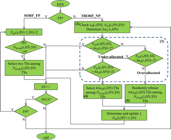
The flowchart of the channel access algorithm.
-
2.
Figure 5 shows an example showing that ship i allocates its time slots per superframe. At one superframe, ship i primarily excludes N BSMF multiframes, that are initially assigned for the base station, among the 15 multiframes of one superframe (see the dotted box (1) in Figure 5). Then, ship i selects two multiframes in descending order of N MFidle (H N,S N,M N) (see the dotted box (2) in Figure 5). If there are more than two multiframes whose N MFidle (H N,S N,M N) values are equal, ship i randomly selects one multiframe among them.
Figure 5 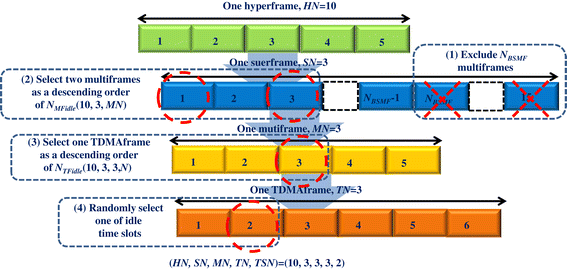
An example of allocating time slots in the SOHF.
-
3.
Ship i selects one TDMAframe of the highest N TFidle (H N,S N,M N,T N) out of the five TDMAframes at the selected multiframe (see the dotted box (3) in Figure 5). If there are more than two TDMAframes whose N TFidle (H N,S N,M N,T N) values are equal, ship i randomly selects one TDMAframe among them.
-
4.
Ship i selects one time slot among the idle time slots at the selected TDMAframe (see the dotted box (4) in Figure 5).
-
5.
Ship i can allocate time slots hyperframe by hyperframe using methods 2 to 4.


In the TROHF of the NP, ship i can allocate more than two time slots according to the number of subscribing ships. Ship i basically needs two time slots for its transmission and four time slots for its subscribing ship’s uplink and downlink transmission per superframe. The number of ship i’s subscribing ships is determined at the end of the current hyperframe HN, in order to determine the number of time slots for the next hyperframe H N+1 at that time. The procedures employed to allocate time slots are as follows:
-
1.
Ship i determines the number of its subscribing ships, n R (i,H N), by referring to the routing table at the end of the current hyperframe HN (see the square box (2) in Figure 4). Let us consider ship k as ship i’s subscribing ship. Then, ship k as well as ship k’s subscribing ships become ship i’s subscribing ships. Thus, n R (i,H N) can be represented as
$$ n{_{R}}(i, HN) = \sum_{k \in {Set}_{R}(i, HN)} \left[ n{_{R}}(k, HN) + 1 \right]. $$((1))Thus, the number of time slots allocated per superframe for the next hyperframe H N+1,N SF (i,H N+1,S N), can be obtained as 4n R (i,H N)+2. Let us define the variation of the number of ship i’s subscribing ships at the end of hyperframe HN as Δ n R (i,H N) which can be expressed as |n R (i,H N−1)−n R (i,H N)|.
-
2.
Ship i checks the status of each superframe SN at hyperframe HN in order to determine N SF (i,H N+1,S N). There are three cases as follows (see the dotted box (3) in Figure 4):
-
(a)
Under-allocated: N SF (i,H N,S N)<4n R (i,H N)+2.
-
(b)
Over-allocated: N SF (i,H N,S N)>4n R (i,H N)+2.
-
(c)
Unchanged: N SF (i,H N,S N)=4n R (i,H N)+2.
In the under-allocated case, N SF (i,H N+1,S N) can be determined case by case according to the values of N SFidle (i,H N,S N) and Δ n R (i,H N);N SF (i,H N,S N) + 4Δ n R (i,H N) in the case of N SFidle (i,H N,S N)≥4 and Δ n R (i,H N)≥1, and N SFidle (i,H N,S N) in the case of N SFidle (i,H N,S N)<4. In the over-allocated case, N SF (i,H N+1,S N) can be obtained as
$$ N_{SF}(i, HN + 1, SN) = N_{SF}(i, HN, SN)\, -\, 4\Delta n{_{R}}(i, HN). $$((2))In the unchanged case, N SF (i,H N+1,S N) is the same as N SF (i,H N,S N).
-
(a)
-
3.
In the under-allocated case, 4Δ n R (i,H N) time slots are additionally assigned (see the square box (4) in Figure 4). The way to allocate additional time slots per superframe depends on Δ N SF which is defined as 15−N BSMF −4Δ n R (i,H N).
-
(a)
In the case of Δ N SF ≥0, ship i selects 4Δ n R (i,H N) multiframes in a similar manner to the allocation of time slots in the SOHF of the FP.
-
(b)
In the case of Δ N SF <0, ship i periodically selects 15−N BSMF multiframes as similarly as allocating time slots in the SOHF of the FP until the number of allocated time slots becomes 4Δ n R (i,H N) at each superframe.
-
(a)
-
4.
In the over-allocated case, 4Δ n R (i,H N) time slots need to be released (see the square box (5) in Figure 4). The way to release time slots per superframe also depends on Δ N SF .
-
(a)
Figure 6 provides an example showing that ship i releases its time slots per superframe. In the case of Δ N SF ≥0, ship i selects 4Δ n R (i,H N) multiframes in ascending order of N MFidle (H N,S N,M N) (see the dotted box (1) in Figure 6). If there are more than two multiframes whose N MFidle (H N,S N,M N) values are equal, ship i randomly selects one multiframe among them. Ship i selects one TDMAframe of the lowest N TFidle (H N,S N,M N,T N) out of the five TDMAframes at the selected multiframe (see the dotted box (2) in Figure 6). If there are more than two TDMAframes whose N TFidle (H N,S N,M N,T N) values are equal, ship i randomly selects one TDMAframe among them. Finally, ship i releases one of the allocated time slots at the selected TDMA frame (see the dotted box (3) in Figure 6).
Figure 6 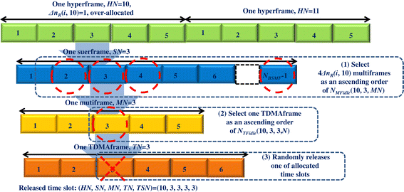
An example of releasing time slots in the TROHF in the NP.
-
(b)
In the case of Δ N SF <0, ship i periodically selects 15−N BSMF multiframes in a similar manner to the release of the time slots in method 4(a) until the number of time slots released becomes 4Δ n R (i,H N) at each superframe.
-
(a)

4 Simulations
In this section, the performance of EASO-TDMA is investigated via simulations and compared to that of ASO-TDMA by considering various network conditions.
4.1 4.1 Conditions
The network conditions for simulations are given as follows:
-
1.
As illustrated in Figure 7, a square-shaped network, which consists of one base station and N ships, is considered. The size of the network is 120 km by 120 km.
Figure 7 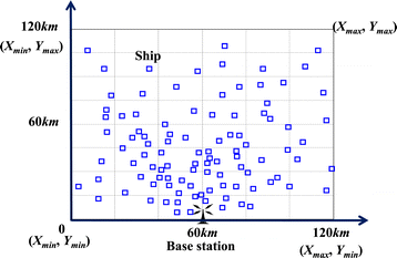
The network topology for the simulation.
-
2.
The position of the base station is stationary and given as (0,60) as shown in Figure 7. N ships are randomly deployed, and their initial positions are randomly determined within the network. The maximum of X- and Y-coordinates for all ships, defined as X max and Y max, are respectively given as 120. The minimum of X- and Y-coordinates for all ships, defined as X min and Y min, are respectively given as 0.
-
3.
All ships move with a velocity in the range of the uniform random variable, v, within the network. The mobility of a ship is modeled as follows:
-
At each simulation time, two uniform random numbers C x and C y are generated, where 0≤C x ,C y ≤1.
-
In the case of C x ≥0.5, the X-coordinate increases as much as v·Δ t, where Δ t is the inter-simulation time, provided that the newly increased X-coordinate is less than X max. Otherwise, the X-coordinate decreases as much as v·Δ t in order to make the ship stay in the given network area during simulation. In the case of C x <0.5, the X-coordinate decreases as much as v·Δ t, provided that the newly decreased X-coordinate is greater than X min. Otherwise, the X-coordinate increases as much as v·Δ t by the same reason.
-
The Y-axis coordinate also increases or decreases as much as v·Δ t with respect to the value of C y as similarly as the way to determine the X-axis coordinate.
-
Finally, the X- and Y- coordinate increment or decrement results in the direction and the distance of a ship’s movement.
-
-
4.
As assumed in [2], all ships and the base station have a maximum communication distance, L, in order to easily achieve ad hoc communication.
-
5.
Among the N ships, there are N a active ships which allocate their time slots, make a route to the base station, and transmit their packet as well as their subscribing ships’ packets.
-
6.
The number of time slots that are allocated by the base station is given as 300 per hyperframe (or frame) for the two MAC protocols. In addition, the number of allocated time slots per sub-frame for ASO-TDMA is given as ten in order to make it equal to the number of allocated time slots per superframe in the SOHF for EASO-TDMA.
-
7.
Both uplink and downlink traffic are considered. All active ships generate n uplink packets per hyperframe which are destined for the base station. The base station also generates n downlink packets per hyperframe, and each packet is destined for one of the active ships that is randomly selected.
-
8.
The length of ingress and egress queues for all ships is fixed as K, and the queueing discipline is simply given as first-in first-out (FIFO). If the queue is found to be full when a packet arrives, the packet is just dropped out.
-
9.
The values for the simulations are given in Table 2.
Table 2 Simulation conditions

The performance parameters considered are the reception success rate (RSR), the collision rate (CR), the end-to-end delay (E2ED), and the channel utilization (CU). First, the reception success rate is defined as the ratio of the number of received packets to the number of transmitted packets and expressed as
where a is the index of active ships (1≤a≤N a ), n RXa is the number of received downlink packets at ship a, n RXbs is the number of received uplink packets, n TXa is the number of the uplink packets transmitted by ship a, and n TXbs is the number of the transmitted downlink packets during the simulation. Second, the collision rate is defined as the ratio of the number of collided packets to the number of transmitted packets and represented as
where n Ca is the number of collided downlink packets at ship a, and n Cbs is the number of collided uplink packets. Third, the end-to-end delay is defined as the multi-hop delay resulting from packet generation at the source to packet reception at the destination, and it is expressed as
where x is the index of successfully received uplink packets from ship a, y is the index of successfully received downlink packets, E2ED ax is the multi-hop delay of the x th downlink packet received by ship a, and E2ED y is the multi-hop delay of the y th uplink packet received by the base station. Fourth, the channel utilization is defined as the ratio of the number of time slots used to the number of time slots per hyperframe, viz 2,250.
4.2 4.2 Results
Figures 8 and 9 illustrate the overall performance of EASO-TDMA and ASO-TDMA and demonstrate that EASO-TDMA outperforms ASO-TDMA, regardless of the network conditions. The confidence level of all simulation results is 95 %. The simulation results are described as follows:

The performance of EASO-TDMA and ASO-TDMA. (a) Reception success rate. (b) Collision rate.

The performance of EASO-TDMA and ASO-TDMA. (a) End-to-end delay. (b) Channel utilt!zation.
-
1.
The reception success rate: EASO-TDMA has a 15 % higher reception success rate than ASO-TDMA on average. The maximum margin is around 25 %, as shown in Figure 8a. The reception success rate of the two MAC protocols decreases as the number of active ships increases. On the other hand, the reception success rate first decreases and then bottoms out with increasing number of packets generated per hyperframe. This implies that the reception success rate mainly depends on the number of active nodes, which increases the possibility of receiver collisions among hidden ships by allocating the same time slots.
-
2.
The collision rate: The performance pattern of the collision rate is opposite to that of the reception success rate. That is, the collision rate of the two MAC protocols increases with the increasing number of active ships because the greater the number of ships engaged in accessing the channel, the higher the chance that the same time slots will be selected. The collision rate of EASO-TDMA is 15 % lower on average than that of ASO-TDMA. In particular, ASO-TDMA can suffer from severe receiver collision when the number of active ships is over 80, because the collision rate is over 50 %, as shown in Figure 8b. This is comparable to the result in [2] in that the collision rate of ASO-TDMA is just 10 % in the case that the number of allocated time slots per sub-frame is one. Thus, it is shown that ASO-TDMA is insufficient to manage receiver collisions in the case where the number of time slots allocated per sub-frame is ten.
-
3.
The end-to-end delay: In contrast to the performance pattern of the reception success rate and collision rate, that of the end-to-end delay is affected more by the number of packets than by the number of active ships, as illustrated in Figure 9a. This is because the queueing delay per ship increases as the number of packets increases, and thus, the multihop delay from the source to the destination also increases. ASO-TDMA results in a 12 times longer end-to-end delay than EASO-TDMA on average. ASO-TDMA results at most in a roughly 22 times longer end-to-end delay than EASO-TDMA. This remarkable performance enhancement results from the fact that each ship allocates as many time slots as there are subscribing ships in order to ease the bottleneck problem.
-
4.
The channel utilization: The channel utilization of EASO-TDMA is 15 % higher on average than that of ASO-TDMA, as shown in Figure 9b. The maximum margin is around 21 %. This result indicates that EASO-TDMA can provide better channel utilization than ASO-TDMA with a lower collision rate because it guides the ships to access the channels more efficiently by avoiding receiver collisions.
5 Conclusions
The SANET was introduced as a technology providing ocean-going ships with VDE services cost-effectively. This paper proposed the MAC protocol for SANETs, EASO-TDMA, which overcomes the weaknesses of the previous approach, ASO-TDMA, and thus enhances the performance of SANETs. The virtue of EASO-TDMA is that it eases the bottleneck problem that occurs at a specific ship by managing the network traffic in a decentralized way. Namely, each ship periodically checks the number of subscribing ships by referring to the routing table and then allocates as many time slots as necessary to manage the traffic from its subscribing ships.
The simulation results showed that EASO-TDMA outperforms ASO-TDMA in terms of the reception rate, collision rate, end-to-end delay, and channel utilization, regardless of the network conditions. In particular, the end-to-end delay of EASO-TDMA is less than 20 s, which is almost 1/12 of that of ASO-TDMA on average. This implies that EASO-TDMA can be efficient for the delay-sensitive VDE services by handling the bottleneck problem. Accordingly, it can be concluded that EASO-TDMA would be an adequate MAC protocol for SANETs. This is an ongoing work. EASO-TDMA will be implemented in SANET systems, and its functionality and performance will be verified through a maritime test for future use.
References
S Lee, J Jeong, M Kim, G Park, A study on real-time message analysis for AIS VDL load management. J. KIIS. 23(3), 256–261 (2013).
C Yun, Y Lim, ASO-TDMA: ad-hoc self-organizing TDMA protocol for shipborne ad-hoc networks. EURASIP WCN. 12(10), 1–16 (2012).
Y Lee, World Radio-communication Conference 2012 (WRC-12). TTA J. 140, 113–117 (2012).
CPG PTC(13) INFO 16, Information paper on VHF data exchange system (VDES). http://www.cept.org/ (Accessed 01-10-2014).
C Yun, S Kim, A Cho, Y Lim, Performance analysis of multiple access protocol for maritime VHF data exchange system (VDES). J. JKIICE. 18(12), 2839–2846 (2014).
C Yun, A Cho, S Kim, J Park, Y Lim, Design of multiband maritime network for ships and its applications. Int. J. KIMICS. 7(3), 314–322 (2009).
IMO FAL-38 INF.2, A study of a data communication network at sea for efficient maritime logistics. https://docs.imo.org/ (Accessed 01-28-2013).
IMO FAL-39 INF.5, A study on enhancing maritime logistics efficiency utilizing maritime VHF digital communication technology and facilitation method. https://docs.imo.org/ (Accessed 08-01-2014).
IMO NCSR-2 INF.9, A study on enhancing maritime logistics efficiency utilizing maritime VHF digital communication technology and facilitation method. https://docs.imo.org/ (Accessed 23-12-2014).
Rec. ITU-R M. 1842-1, Characteristics of VHF radio systems and equipment for the exchange of data and electronic mail in the maritime mobile service RR Appendix 18 channels. http://www.itu.int/rec/R-REC-M.1842/en (Accessed 06-09-2009).
Rec. ITU-R M.1371-5, Technical characteristics for a universal ship borne automatic identification system using time division multiple access in the VHF maritime mobile band. http://www.itu.int/rec/R-REC-M.1371/en (Accessed 01-02-2014).
SOLAS, International Convention for the Safety of Life at Sea (SOLAS). https://docs.imo.org/ (Accessed 18-02-2015).
COLREGS, International Regulations for Preventing Collisions at Sea. https://docs.imo.org/ (Accessed 15-05-2014).
ITU-R SG5 WP5B working doc, VHF data link protocols for data communication systems in the maritime mobile service band. https://www.itu.int/md/R07-WP5B-C-0601/en (Accessed 04-11-2010).
ETSI EN 300 392-2, Terrestrial Trunked Radio (TETRA): voice plus data (V+D); Part2: Air Interface (AI). http://www.itu.int/itu-t/workprog/wp-a5-out.aspxisn=2972 (Accessed 01-08-2010).
Acknowledgements
This work was conducted as a part of the research project ‘Development of marine RF based ad-hoc network for ship’ and was financially supported by the Ministry of Land, Transport and Maritime Affairs (MLTM) of Korea.
Author information
Authors and Affiliations
Corresponding author
Additional information
Competing interests
The authors declare that they have no competing interests.
Rights and permissions
Open Access This article is distributed under the terms of the Creative Commons Attribution 4.0 International License (https://creativecommons.org/licenses/by/4.0), which permits use, duplication, adaptation, distribution, and reproduction in any medium or format, as long as you give appropriate credit to the original author(s) and the source, provide a link to the Creative Commons license, and indicate if changes were made.
About this article

Cite this article
Yun, C., Lim, Yk. EASO-TDMA: enhanced ad hoc self-organizing TDMA MAC protocol for shipborne ad hoc networks (SANETs). J Wireless Com Network 2015, 84 (2015). https://doi.org/10.1186/s13638-015-0322-5
Received:
Accepted:
Published:
DOI: https://doi.org/10.1186/s13638-015-0322-5