- Research
- Open access
- Published:
An intelligent solar energy-harvesting system for wireless sensor networks
EURASIP Journal on Wireless Communications and Networking volume 2015, Article number: 179 (2015)
Abstract
An intelligent solar energy-harvesting system for supplying a long term and stable power is proposed. The system is comprised of a solar panel, a lithium battery, and a control circuit. Hardware, instead of software, is used for charge management of the lithium battery, which improves the reliability and stability of the system. It prefers to use the solar energy whenever the sunshine is sufficient, and the lithium battery is a complementary power supply for conditions, such as overcast, rain, and night. The system adapts a maximum power point tracking (MPPT) circuit to take full advantage of solar energy, and it ensures the lithium battery an extremely long life with an appropriate charging method, which shortens the frequency of the battery charge-discharge cycle. This system can be implemented with small power equipment which is especially suitable for outdoor-based wireless sensor nodes in the Internet of Things (IOT).
1 Introduction
Wireless sensor network (WSN) is the second largest network after the Internet in the world, and it ranks as the first of the next ten emerging technologies. Currently, it has been used widely in the Internet of Things (IOT), mainly for environmental parameter monitoring in various production circumstances, such as greenhouse [1, 2], water quality monitoring [3, 4] and so on.
Conventionally, disposable batteries can be used for power supply in WSN, where researchers have made efforts to save the finite battery on power control by routing algorithm and topology optimization [5–7]. On the other hand, reducing the power consumption of the nodes always sacrifices performances like computing. The most up-to-date power density of available battery technology cannot match the needs of most WSN for long lifetime and small form factor, which limits the use of WSN due to the need for large batteries. It also has a slight possibility that the better batteries for small devices will become available in the next few years. Energy harvesting and management may be the most convenient ways to solve the problem of making WSN autonomous and enable widespread use of these systems in many applications [8].
The state-of-the-art energy-storage techniques for energy-harvesting systems in sustainable wireless sensor nodes can be classified into two technologies, i.e., supercapacitors and rechargeable batteries [9]. These two categories have their own advantages and disadvantages, involving energy-storage density, lifetime, discharging, leakage, size and so on [10]. Since the supercapacitors have significantly lower power density and higher leakage overhead than rechargeable batteries [11], which makes them impractical for small-package WSN nodes, we employ an energy-harvesting system using a lithium battery as the storage.
From the electrochemical theory, we may learn that the aging of the lithium battery is influenced greatly by the self state of charge (SOC) [12–14]. Data from [15] show that lithium batteries in high SOC are more vulnerable to environmental impacts of aging and SOC cycling the batteries enhances the resistive lives. Therefore, it must be avoided that the battery always be in high SOC to extend battery lifetime, and approaches, one example of which is recharging the battery until its voltage drops below a specific level, should be taken [16]. The charging managements are usually employed by microcontrollers for the flexibility of software designing and implementation [9, 17], but researchers [18] have proven that battery-charging controlled by software may have some problems in which charging logic could not work, and that the battery could not be charged under sufficient sunlight. In our system, the charging management is implemented by hardware instead of the codes running within the microcontroller for consideration of reliability.
This paper focuses on an intelligent solar energy-harvesting (ISEH) system based on maximum power point tracking (MPPT) for wireless sensor nodes used in IOT, which prefers to use the solar power and takes the lithium battery as a supplementary under the condition of inadequate illumination. To prolong the lithium battery life, an intelligent circuit using RS triggers is proposed, which makes the lithium battery charge only when the battery voltage is lower than a specific value. The circuit can be divided into two main functional parts, i.e., the charging sub-circuit and the control sub-circuit. The sub-circuits are merged into one printed circuit board (PCB), and the whole system has been designed, built, and tested. Experimental results show that the system can work stably and quite fit the requirements of pre-designing.
The contributions of this paper for the ISEH systems are as follows:
-
(1)
Charging control of the lithium battery is implemented dexterously by RS triggers, which supports a reliable and stable operational status for the system contrasting the approach executed by software.
-
(2)
We combine the advantages of other solar-harvesting systems, which are dominated by solar power using a lithium battery as an energy storage and only when the battery voltage drops below a specific level before charging it. This architecture will help extend the life of the battery and the system, and avoid wasting the solar energy.
The construction of this paper is organized as follows. In Sec. 1, we give an introduction of our study. A brief review on the related work is outlined in Sec. 2. Then, we present the problems in solar energy-harvesting systems and the proposed system construction in Sec. 3. In Sec. 4, the corresponding calculations of some important parameters are shown. In Sec. 5, we provide the functional module implementation of the system; simulation and experimental results are also included in this section. In Sec. 6, a conclusion of this paper is made.
2 Related work
Self-sustainable WSN systems are on the verge of being a broad requirement in many fields [19, 20], since most of WSN applications are difficult to maintain after their deployments. Researchers make great efforts to find out renewable energy resources from the environment for WSN usage, such as solar power, wind, vibration, heat, and RF [9]. How to collect and store energy effectively from the environment has been taken more and more seriously by researchers.
Sharma et al. [21] studied a sensor node with an energy-harvesting source, and a buffer was used to store the generated energy. The sensor node periodically sensed a random field and generated packets. Only when the energy was available, the packets would be transmitted; otherwise, they were stored and waited upon. They also exploited throughput optimization, i.e., to obtain energy management policies for the largest possible data rate and the minimal mean delay in the queue. In order to increase the lifespan of WSN with powering-up methods, Ramasur et al. [22] took some efforts in a wind energy harvester (WEH) model. Their WEH consisted of a wind generator and a power management unit to store and condition the generated energy. The results showed that their aero-elastic flutter generator could produce more power compared with that of the other small-scale wind generators; however, the circuit was not equipped with maximum power point tracking (MPPT) resulting in poor efficiencies of the WEH.
Besides harvesting the wind power, taking full advantage of the solar power may be more convenient in WSN usage. Although solar power is time- and season-dependent, it remains as one of the best choices by adapting a power management mechanism [23]. Yi et al. [24] put forward a wireless sensor node design based on a solar energy-power supply. They gave full consideration to energy-saving principles by adapting low-power consumption devices in every module and collected the solar energy to provide lasting power for the system.
Another low-power solar energy-harvesting system for WSN was put forward in [25], where Naveen et al. employed the system in an intelligent building. They adapted a solar energy harvester instead of an alkaline battery for the sensor nodes. They used a number of solar cells connected in series and parallel to each other to scavenge energy, and they applied a set of ultracapacitors to store up the energy. As a backup energy source, alkaline batteries were connected along with the capacitors.
A solar-powered sensor module using low-cost capacitors as storage buffers was investigated in [26], and only capacitors were adapted. The advantage is that the energy-charging time is shortened within a second, although the module cannot work without light illumination. A battery-supercapacitor hybrid energy-storage module was proposed in [17], and an embedded processor was used to control the charging of the battery. Supercapacitors charge the battery only when their saved energy exceeds the peak requirements of processors running at full speed and ignores estimating the SOC of the battery.
Taneja [27] et al. brought forward a kind of micro photovoltaic energy system. Alberola et al. [28] put forward another solar power system consisting of a supercapacitor and a lithium battery. To provide an uninterrupted power supply, the literature [29] exploited two battery groups for energy storage. In charging lithium batteries, some literatures have been presented [30–32]. The common method is that whenever the voltage of the solar panel is high enough, charging starts. According to the research of Ecker et al. [15], Takahashi et al. [33], and Liu et al. [34], the lithium battery capacity could fade rapidly when it is in high SOC for a long term; thereby, Jiang et al. [16] and Li et al. [35] have proposed a solution that the system charges the lithium battery only when the voltage is lower than a specific value. This strategy can solve the problem of charging too often and the lithium battery being in high SOC all the time; nevertheless, it may waste most of the solar power in that this system applied the lithium battery as the primary power source no matter how capable the solar panel was to supply the system or not.
3 Methodology
In this section, to begin with, we analyze some shortages of the existing solar energy-harvesting systems and then present the methodology and the hardware components of our system.
3.1 Problems to be considered
Energy harvesting is one of the most promising technologies toward the goal of perpetual operation of WSN. Recent developments have allowed renewable energy sources such as solar or wind power to be used for wireless sensor nodes. Concerning the usage of solar energy, a lot of scholars have conducted considerable research works, while there are still some aspects which could take more optimization.
-
(1)
Making full use of the solar energy is very important. The system employs the solar power as the preferential power source as long as the sunshine is available [27–29], rather than that which takes the rechargeable battery as the primary one and applies the solar energy only for charging.
-
(2)
To extend the rechargeable battery life as far as possible and keep the high performance of the battery, the charging process of the battery should be taken into control, avoiding too many charge-discharge cycles or the battery will always be in a high-charge state.
-
(3)
Designing a simple and ingenious control circuit can reduce the complexity of system development, decrease the power consumption, and increase the stability and reliability of the system.
According to the survey of the related work, many researchers provide better solutions to the first two points mentioned above; however, the last point on how to improve the stability and reliability of the circuit needs to be researched further. Common energy management and charge control are always achieved by software, while in cases of extreme discharges, the microcontroller itself may be powered off and cannot be restarted even if there is sufficient illumination, leading to the question, how could the battery be charged? In this paper, we focus on application of hardware realization of charge management, which can greatly improve the robustness of the solar-harvesting system.
3.2 System construction
The ISEH system is physically composed of a solar panel, a lithium battery, and a control circuit. The control circuit comprises a solar MPPT module, a charging sub-circuit, an over-discharged protection sub-circuit, and a boost DC/DC module for the lithium battery. The system schematic diagram is shown in Fig. 1.

Scheme for the ISEH System
As shown in Fig. 1, the system has three input branches, i.e., a solar panel, a lithium battery, and a mini-USB interface. It also has an output branch offered by an ordinary USB interface. In this paper, we use “bimodule” to emphasize that the output of the system may originate from the solar panel or the lithium battery, respectively. The standard mini-USB interface is a reservation to charge the lithium battery by an external power adapter if necessary. The functional components of the system are demonstrated as follows:
-
(1)
Solar power supply
We propose a new solution for supplying the power to the sensor nodes, contrasting with that in [28] and [31]. In those two papers, the task of the solar power is only for charging the lithium battery and the super capacitor by a DC/DC converter, which may cause part of the solar energy to be wasted. While in our work, the solar branch has the priority to provide electrical power to make full use of its energy unless overcast, rainy days, or night etc. comes. The power generated via this branch flows to the MPPT module first. The MPPT guarantees that the system can utilize the almost peak power produced by the solar panel, and the principle of MPPT are shown in Fig. 2.
Fig. 2 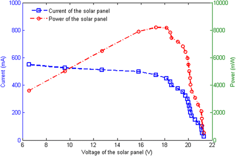
Power, voltage and current of the solar panel
When the solar panel meets a light load or comes very close to opening a circuit, the output voltage may approach the highest level. The power and the current are simultaneously very small. As the load becomes heavier, there are many changes that will be made until it reaches the peak value and then gradually declines. For example, the output voltage of the solar panel being decreased, the current being increased more rapidly, and the power being increased gradually as a synthesis. The MPPT circuit helps the output voltage of the solar panel stay around the peak power area. Therefore, the system can apply it with maximum efficiency [36, 37].
-
(2)
Lithium battery power supply
As shown in Fig. 1, a mechanical single-pole single-throw (SPST) switch (3) is located following the lithium battery, which can deter the lithium battery from wasting energy in an open circuit and keep it safe in the case of transportation or stock. After system deployment, the switch should be switched on manually. If the power provided by the solar panel cannot satisfy the load, the voltage comparator (2) drives the switch (2) to connect to port B, which disconnects the solar branch and connects the lithium branch to the system output. A protection circuit is placed right after the battery to avoid overdischarge, followed by a DC/DC boost circuit to raise the voltage from battery nominal voltage to system output voltage. Most of the values used in this paper are listed in Table 1.
Table 1 Summary of values -
(3)
Charging circuit
In Fig. 1, the switch (1) is an electronic SPST which controls the charging status of the lithium battery. It maintains the switch-off status as default, which means that the battery is not charged. If and only if the battery voltage is underneath the predefined level, the voltage comparator (1) triggers the switch (1) on, and the battery is charged at once if the solar panel could afford it. As soon as the charging starts for a few seconds, the battery voltage rises rapidly and changes the state of the comparator (1). That is why a RS trigger is required to keep the charging status. The control chip of the charging circuit is CN3063 [38]. As charging is terminated, the pin END of the chip changes to low level, which turns the switch (1) off and disconnects the charging circuit. The switch status is also maintained by the RS trigger.

4 System parameters analysis
4.1 Power consumption of node
In applications of IOT, WSN nodes are generally divided into the following three categories; the sensor nodes, the routing nodes, and the sink node. The power consumption of the sink node is usually the largest, but it can be deployed indoors or easy to approach outdoors, so it is unnecessary to consider its power supply. In terms of hardware construction, the sensor nodes usually have more sensors than the routing nodes, for example, the dissolved oxygen sensor, PH sensor etc. The total power consumption of the sensor group is larger than that of the sensor node itself, consumed by data computing and radio transmission, so that the power consumption of the sensor nodes is larger than that of the routing nodes. In the system design, power consumption of the sensor nodes should be taken into the overriding consideration.
In our research, the sensor nodes usually include the following components:
-
(1)
ARM Cortex-M0
-
(2)
ZigBee module
-
(3)
Sensors (dissolved oxygen, PH, temperature etc.)
The power consumption of all the components is calculated as shown in Table 2. V in represents the input voltage, which is the ISEH system output voltage. The notation I stands for the average current. Especially, the data given in the table are the maximum or close to it. Each of the sensor’s current consumption is set to the average operating current. The notation T stands for the working hours in one day, 2 h in a day means the duty cycle of 8.33 %, that is to say, a data monitoring period lasts for 5 min every hour. As a kind of statistical result, the power consumption of one sensor node is about 0.92 Wh every day.
4.2 Battery selection
Comparison of common rechargeable batteries is shown in Table 3. Numbers 1–5 represent lead-acid battery, nickel-cadmium battery, nickel-hydrogen battery, lithium-ion battery, and lithium-polymer battery, respectively.
As demonstrated in Table 3, the lithium-polymer battery is relatively satisfactory for the system usage, whose capacity depends on the capacity of the load and the longest rainy days of the system-deployed region.
4.3 Calculation of battery capacity
The calculation formula of the battery capacity (BC) is given by
In this expression,
-
A - Safety factor, between 1.1–1.4
-
QL - The average daily power consumption of the load, Wh
-
NL - The longest continuous rainy days, set 7 according to the experience
-
TO - Temperature correction factor, in general, TO = 1 when temperature is above 0 °C, and TO = 1.1 above −10 °C and TO = 1.2 below −10 °C.
-
cc - The depth of battery discharge, generally speaking, if it is a lead-acid battery, the value is 0.75, if it is a nickel-cadmium battery, the value is 0.85, and if it is a lithium battery, the value is 0.80. In our research, the lithium battery would not be charged until its voltage dropped under a specific level, and it should provide the system with the rest energy just in case there is no sunshine for charging, namely, even when the battery voltage is reduced to the charging boundary, it still persists that appropriate energy as a backup should be considered, so the value of cc is set to 0.6.
Combined with the data from above, the battery capacity is calculated to be about 3190−4061 mAh (for the nominal voltage of a lithium-polymer battery). Since the calculation is made with safety allowance, the battery capacity can be set to 4000 mAh.
5 Simulation and implementation
In this section, the performance of the proposed ISEH system is simulated and compared with two types of existing solar energy-harvesting systems [16, 30–32, 35], then we gave the design details of each module in the ISEH system. Finally, we have implemented an experimental circuit, as shown in Fig. 9, which was tested with output characteristics of the system.
5.1 Performance simulation
Based on the analysis mentioned above, simulations are taken for demonstrating the differences between the ISEH system and the other systems. The parameters used in the simulations are shown in Table 4.
It is worth noticing that the duty cycle is set to 1, which means that the node works all the time with full power consumption, and the sunshine performs a regular pattern like a square wave, which is unreal for the actual weather condition. All the settings are adapted only for the reason of facilitating the contrast effect. Results given in Fig. 3 are a comparison between the ISEH system and the previous system which could charge when the sunlight is sufficient (CWSS), which charges the battery as long as there is sufficient illumination.

Simulation result between the ISEH and CWSS system
In Fig. 3, the green line represents the lithium battery-voltage curve of the ISEH system and the red line represents that of the CWSS system; the dashed red line parallel to the horizontal axis is the charging threshold, and the dashed black square waves represent the intensity of the sunshine. The blue curve is a reference, one that represents the continuous discharge of the lithium battery voltage without charging. As shown in the figure, the lithium battery of the ISEH system discharges only when the sunshine is insufficient, and it is charged once during the whole 40 h. Relatively, the charge-discharge cycle of the CWSS system is six times, which is far more than that of the ISEH system. At the same time, it is SOC also in a high level most of the period. As a matter of fact, the real weather condition cannot be regular like that, so the number of the cycle is usually more than that shown in this simulation, which has a great influence on the life of lithium batteries.
Figure 4 shows the comparison result between the ISEH system and the other system which uses the lithium battery as the main power supply (BMPS) and charges it only when its voltage is beneath a specific level. The parameters used in the simulations are also shown in Table 4. Except for the red curve with “o” which represents the battery voltage of the BMPS system, the rest of the curves are the same as that shown in Fig. 3.

Simulation result between the ISEH and BMPS system
As shown in Fig. 4, the BMPS system makes a little improvement, because the charge-discharge cycle is less than that of the CWSS system shown in Fig. 3. But whatever the weather is, the lithium battery is the main power source, which causes a waste of the solar energy and makes the discharge rate larger than that of the ISEH system, thus the number of charge-discharge cycles is also more than that of the ISEH system.
5.2 Detailed design
According to the principle of the system composition, each function module of the system is taken into detailed circuit design. The main functional module realization is described as follows.
5.2.1 MPPT module
The MPPT module is based on chip MP2307 which uses an autonomous tracking strategy to provide an upmost power supply for the system. The input of the module is the output voltage of the solar panel, and the output of it is the normal voltage.
5.2.2 Charging module
This module is based on the charging management chip CN3063 [38] which is produced by the Consonance Electronic Co. Ltd. The function of this module provides an intelligent method to charge the lithium battery.
The input of this module is from the MPPT circuit, and the output is connected to the lithium battery. CN3063 is a single lithium battery-charging management chip, which can be easily powered by a solar panel with a wide range of input voltage. An on-chip 8-bit ADC can adjust the charging current automatically. Its regulation voltage can be adjusted by an external resistor, and the charging current can also be programmed externally with a single resistor. The charging process of CN3063 is drawn in Fig. 5 [38].

Charging profile of CN3063
The lithium battery-charging process is generally divided into the following three phases:
-
(1)
Pre-charge phase
-
(2)
Constant current phase
-
(3)
Constant voltage phase
The first phase is carried out only when the lithium battery voltage is very low. Usually, the second and the third phase occupy most of the charging process. The constant current of charging can be regulated externally, and the continuous programmable charge current can reach 600 mA.
In the second step, the calculation formula of charging current is given by
-
I CH - charging current, with unit A
-
R ISET - the resistance from the ISET pin of the CN3063 to ground, with unit Ω
For example, if the system requires a charging current of 500 mA, R ISET can be calculated as follows:
To ensure good stability and temperature characteristics, R ISET recommends the use of a metal film resistor with an accuracy of 1 %.
When charging continues, the level of the \( \mathrm{CHRG}- \) pin drops down by an internal switch, which indicates that the charging is in progress; otherwise, the pin is in a high-impedance state. This pin can be used to indicate whether the battery is being charged or not by an external LED.
When the charging is terminated, the level of the \( \mathrm{D}\mathrm{O}\mathrm{N}\mathrm{E}- \) pin drops down by an internal switch; otherwise, the pin is in a high-impedance state. The pin’s low level can be used as the input signal to the RS trigger, and it turns the trigger over and maintains the status, which ensures that the lithium battery cannot be charged until its voltage drops below the predefined level again.
5.2.3 Boost module
There are some differences between the battery nominal voltage and the system output voltage; therefore, it is necessary to use a DC/DC boost circuit to make the conversion. GS1661 is a current mode boost DC/DC converter, and it is available in SOT23-6 L package and provides space-saving PCB for applications. The chip can be implemented with fewer external components.
The proposed module can raise voltage from 3.3–4.2 V to the system output voltage, and the output voltage can be determined by two external resistors
The peak current can also be determined by an external resistor R e3, the expression is
5.2.4 Control module of branch choosing
Since the ISEH system has two branches for power supply, a switching control circuit as shown in Fig. 6 is needed.

Power supply circuit switching module
LM339 is a voltage comparator (U4A), and it has two inputs, the inverted input as a reference which is provided by a three-terminal regulator (OUTPUT) and the positive-going input which is provided by the MPPT output voltage. When the positive-going input voltage is higher than the reference, LM339 provides a high-level output, which makes Q1 (9013) switch on and drives the pin G of the Mosfet (U3) down; thus, U3 breaks over, and the system selects the solar panel for power support. At the same time, pin 1 of U4A is high, which makes ST2301 (U13) and Mosfet (U6) both go off and then the output of the lithium battery is closed.
On the other hand, when the positive-going input voltage is beneath the reference, the output voltage of U4A should be low, and ST2301 (U13) switches on making U6 break over. As a matter of fact, the lithium battery provides the power instead of the solar panel.
5.2.5 Charge control and over discharge protection
To prolong the life of the lithium battery, lengthening the charge-discharge cycle as long as possible is undoubtedly a good approach. Li et al. used a microcontroller to realize the charging progress, which is convenient and makes it easy to change some strategies, and it merely seems slightly more complicated for programming [35]. In this paper, we deploy a sophisticated method using RS triggers to implement this function with less cost. Consequently, it is more stable compared with the crash possibility of the microcontroller.
The charge control and over discharge protection circuit is shown in Fig. 7.

Charge control and over discharge protection
The lifetime of the lithium battery determines the life of the entire system. Based on the premise of not affecting the system work, reducing the charge-discharge cycles of the battery is very helpful. Experimental results show that the lithium battery can work for a long time when its voltage is between 3.7–3.9 V, but if the voltage is lower than the threshold, it drops rapidly with discharge going on. So the lithium battery should be charged at once when its voltage is under the threshold. Critically, if the battery voltage is lower than the danger boundary, it may be eternally damaged, so discharge should be stopped immediately, and the system has to do something to avoid this from happening [35].
According to the circuit in Fig. 7, when the battery voltage is lower than the threshold (whose value can be adjusted by the resistor R14 and R18), the output of U4B in LM339 and the pin \( 2\mathrm{R}- \) of RS trigger (U10) are both low. Since the battery is not fully charged, the pin \( \mathrm{D}\mathrm{O}\mathrm{N}\mathrm{E}- \) of CN3063 is in a high-impedance state according to its data sheet. Therefore, the pin \( 2\mathrm{S}- \) of U10 is high. Based on the function table of RS trigger as shown in Table 5, the output Q of RS trigger should be low, thus the Mosfet U9 is conducted, and the system starts to charge the battery.
Once the battery voltage is higher than the threshold with continuous charging, the level of \( 2\mathrm{R}- \) changes from low to high, and \( 2\mathrm{S}- \) remains at a high level at the same time because charging has not finished yet. According to Table 5, the output of the RS trigger maintains the former state, and the system still continues to charge the battery.
When the battery has been charged, the pin \( \mathrm{D}\mathrm{O}\mathrm{N}\mathrm{E}- \) of CN3063 converts to low, and the pin \( 2\mathrm{S}- \) is also being low. Simultaneously, the pin \( 2\mathrm{R}- \) remains high, so the RS trigger outputs high levels, and the charging circuit is disconnected. The pin \( \mathrm{D}\mathrm{O}\mathrm{N}\mathrm{E}- \) turns to being in a high-impedance state once again, which makes the level of \( 2\mathrm{S}- \) high, and \( 2\mathrm{R}- \) also maintains a high state, thus the RS trigger remains in a Q0 state of high level, which means the circuit is out of the charging process.
RS trigger realizes an intelligent charging strategy. When the lithium battery voltage falls below the threshold, the charging circuit will switch on. Subsequently, when the battery is fully charged, the circuit will disconnect at once. It would not be turned on until the battery voltage drops beneath the threshold again. All the descriptions in time sequence are shown in Fig. 8.

The RS trigger sequence diagram
In addition, the system also has an over-discharged protection module. When the lithium battery voltage is lower than the protection (the value can be adjusted by two resistors), U12 (ST2301) is disconnected, which cuts off the lithium battery power output to protect the battery from overdischarge.
5.3 Experimental results
A circuit board for testing is made as shown in Fig. 9. The ISEH system is constructed based on the board, which could provide uninterrupted power supply for the WSN nodes. The system is tested under daylight illumination, and the experimental results show that the system can switch the power supply branch automatically and work stably. When the lithium battery voltage drops underneath the predefined level, the lithium battery can be charged as soon as possible if the illumination is sufficient.

Circuit board
As shown in Table 2, the power consumption of one sensor node is 460 mW. We can get two different operating points in the conditions of solar power or lithium battery-branch energy supply, as shown in Fig. 10a. The reason causing the operating points to be different is that the output voltage of the two branches have a slight difference in the circuit. Whether the power is provided by the solar or the lithium branch, the power efficiency (as shown in Fig. 10b) is higher than 60 %. It is worth mentioning that the power efficiency is up to 80 % with the lithium battery as a power supply. From Fig. 10b we can find that the efficiency of the solar power branch is lower than that of the lithium branch, and at the same time, the former is more sensitive with the load resistance. The reasons for this phenomenon can mainly be concluded in two parts. The first one is that the voltage difference between input and output of the solar branch is larger than that of the battery branch, and the second is that the former components cause more power loss than that of the latter.

Output characteristics of the ISEH system. a Power conversion efficiency versus load resistance. b Output power versus load resistance
6 Conclusions
In this paper, a novel intelligent solar energy-harvesting system is designed by using an MPPT circuit. Hardware, instead of software, is used for charging management of the lithium battery, which can enhance the robustness of the system greatly. Analyses based on power supply requirements are made for WSN nodes in IOT. The system can afford a stable power supply with 5-V output voltage through a standard USB interface. Lithium battery-charging strategy can also ingeniously avoid the charge-discharge cycle a lot, and thus the lifetime of the lithium battery can be greatly extended. Experimental results demonstrate that the system can switch the power supply branch automatically. When the voltage of lithium battery drops below the predefined level, it can be charged properly. The system performs stably and safely with high reliability, high efficiency, low-power loss, and simple composition.
References
ZhouY, Yang X, Guo X, et al. A design of greenhouse monitoring & control system based on ZigBee wireless sensor network. IEEE. Int. Conf. WiCOM, (IEEE, Shanghai, 2007), pp. 2563–2567
Ahonen T, Virrankoski R, Elmusrati M. Greenhouse monitoring with wireless sensor network. IEEE/ASME. Int. Conf. on MESA, (IEEE/ASME, Beijing, 2008), pp. 403–408
Nasser N, Zaman A, Karim L, et al. CPWS: An efficient routing protocol for RGB sensor-based fish pond monitoring system. IEEE. 8th. Int. Conf. WiMob, (IEEE, Barcelona, 2012), pp. 7–11
O’Flyrm B, Martinez R, Cleary J, et al. Smart Coast: a wireless sensor network for water quality monitoring. IEEE. 32nd. Conf. LCN. 2007;815–816.
GS Arumugam, T Ponnuchamy, EE-LEACH: development of energy-efficient LEACH Protocol for data gathering in WSN. EURASIP. J. Wireless. Commun. Netw. 1, 76 (2015). doi:10.1186/s13638-015-0306-5
I Butun, I Ra, R Sankar, PCAC: power-and connectivity-aware clustering for wireless sensor Networks. EURASIP. J. Wireless. Commun. Net. 1, 83 (2015). doi:10.1186/s13638-015-0321-6
G Anastasi, M Conti, M Di Francesco et al., Energy conservation in wireless sensor networks: a survey. Ad. Hoc. Netw. 7(3), 537–568 (2009)
RJM Vullers, RV Schaijk, HJ Visser et al., Energy harvesting for autonomous wireless sensor networks. IEEE. Solid State Circuits. Mag. 2(2), 29–38 (2010)
F Akhtar, MH Rehmani, Energy replenishment using renewable and traditional energy resources for sustainable wireless sensor networks: a review. Renew. Sustain. Energy Rev. 45, 769–784 (2015)
VA Boicea, Energy storage technologies: the past and the present. Proc. IEEE. 102(11), 1777–1794 (2014)
Z Xu et al., Electrochemical supercapacitor electrodes from sponge-like graphenenano architectures with ultrahigh power density. J. Phys. Chem. Lett. 3(20), 2928–2933 (2012)
W Waag, S Käbitz, DU Sauer, Experimental investigation of the lithium-ion battery impedance characteristic at various conditions and aging states and its influence on the application. Appl. Energy. 102, 885–897 (2013)
M Broussely, P Biensan, F Bonhomme et al., Main aging mechanisms in Li ion batteries. J. Power. Sources. 146(1), 90–96 (2005)
J Vetter, P Novák, MR Wagner et al., Ageing mechanisms in lithium-ion batteries. J. Power. Sources. 147(1), 269–281 (2005)
M Ecker, JB Gerschler, J Vogel et al., Development of a lifetime prediction model for lithium-ion batteries based on extended accelerated aging test data. J. Power. Sources. 215, 248–257 (2012)
Jiang X, Polastre J, Culler D. Perpetual environmentally powered sensor networks. IEEE. 4th. Int Symp. IPSN, (IEEE, Los Angeles, 2005), pp. 463–468
Xiang Y, Pasricha S. Run-time management for multicore embedded systems with energy harvesting. 2015. doi:10.1109/TVLSI.2014.2381658
Dutta P, Hui J, Jeong J, et al. Trio: enabling sustainable and scalable outdoor wireless sensor network deployments. Proc. 5th. Int. Conf. Info. Process. Sensor. Netw, (ACM, Nashville, TN, 2006), pp. 407–415
A Berger, LB Hörmann, C Leitner et al., Sustainable energy harvesting for robust wireless sensor networks in industrial applications (Sensor Applications Symposium SAS, Zadar, 2015)
Dall’Ora R, Raza U, Brunelli D, et al. SensEH: From simulation to deployment of energy harvesting wireless sensor networks. IEEE. 39th. Conf. Local. Comput. Netw. Workshops, (IEEE, Edmonton, AB, 2014), pp. 566–573
V Sharma, U Mukherji, V Joseph et al., Optimal energy management policies for energy harvesting sensor nodes. IEEE. Trans. Wireless. Commun. 9(4), 1326–1336 (2010)
Ramasur D, Hancke G P. A wind energy harvester for low power wireless sensor networks. IEEE. Int. Conf. I2MTC, (IEEE, Graz, 2012), pp. 2623–2627
JA Khan, HK Qureshi, A Iqbal, Energy management in wireless sensor networks: a survey. Comput. Electr. Eng. 41, 159–176 (2015)
Y Gao, G Sun, W Li et al., Wireless sensor node design based on solar energy supply. IEEE. 2nd. Int. Conf. PEITS 3, 203–207 (2009)
Naveen K V, Manjunath S S. A reliable ultra-capacitor based solar energy harvesting system for wireless sensor network enabled intelligent buildings. IEEE. 2nd. Int. Conf. IAMA, (IEEE, Chennai, 2011), pp. 20–25
Chuang WY, Lee CH, Lin CT, et al. Self-sustain wireless sensor module. IEEE Int Conf Internet Things Green Computing Commun Cyber Physical Soc Computing 2014;288–291
Taneja J, Jeong J, Culler D. Design, modeling, and capacity planning for micro-solar power sensor networks. Proc. 7th. IEEE. Int. Conf. IPSN, (IEEE Computer Society, St. Louis, Missouri, 2008), pp. 407–418
Alberola J, Pelegri J, Lajara R, et al. Solar inexhaustible power source for wireless sensor node. IEEE. Proc. IMTC, (IEEE, Victoria, BC, 2008), pp. 657–662
Bhuvaneswari P T V, Balakumar R, Vaidehi V, et al. Solar energy harvesting for wireless sensor networks. IEEE. 1st. Int. Conf. CICSYN, (IEEE, Indore, 2009), pp. 57–61
Isaacson M J, Holl. Sworth R P, Giampaoli P J, et al. Advanced lithium ion battery charger. IEEE. 15th. BCAA, (IEEE, Long Beach, CA, 2000), pp. 193–198
F Ongaro, S Saggini, P Mattavelli, Li-ion battery-supercapacitor hybrid storage system for a long lifetime photovoltaic-based wireless sensor network. IEEE. Trans. Power. Electronics. 27(9), 3944–3952 (2012)
H He, R Xiong, X Zhang et al., State-of-charge estimation of the lithium-ion battery using an adaptive extended Kalman filter based on an improved Thevenin model. IEEE. Trans. Veh. Technol. 60(4), 1461–1469 (2011)
K Takahashi, M Saitoh, N Asakura et al., Electrochemical properties of lithium manganese oxides with different surface areas for lithium ion batteries. J. Power. Sources. 136(1), 115–121 (2004)
YJ Liu, XH Li, HJ Guo et al., Electrochemical performance and capacity fading reason of LiMn2O4/graphite batteries stored at room temperature. J. Power. Sources. 189(2), 721–725 (2009)
X Li, Y Wu, G Li et al., Development of wireless soil moisture sensor base on solar energy. Trans. CSAE. 26(11), 13–18 (2010)
D Brunelli, C Moser, L Thiele et al., Design of a solar-harvesting circuit for batteryless embedded systems. IEEE. Trans. Circuits. Syst I: Regul. Pap. 56(11), 2519–2528 (2009)
T Esram, PL Chapman, Comparison of photovoltaic array maximum power point tracking techniques. IEEE. Trans. Energy. Conversion. EC. 22(2), 439 (2007)
CN3063 datasheet, Shanghai Consonance Electronics Co. Ltd., http://www.consonance-elec.com/pdf/datasheet/DSE-CN3063.pdf.
Acknowledgements
This work was supported by the Hunan Provincial Natural Science Foundation of China under Grant 14JJ5009, the Post Doctoral Foundation of Central South University, China, and the National Natural Science Foundation of China (61272495, 61379153, and 61401519).
Author information
Authors and Affiliations
Corresponding author
Additional information
Competing interests
The authors declare that they have no competing interests.
Rights and permissions
Open Access This article is distributed under the terms of the Creative Commons Attribution 4.0 International License (https://creativecommons.org/licenses/by/4.0), which permits use, duplication, adaptation, distribution, and reproduction in any medium or format, as long as you give appropriate credit to the original author(s) and the source, provide a link to the Creative Commons license, and indicate if changes were made.
About this article

Cite this article
Li, Y., Shi, R. An intelligent solar energy-harvesting system for wireless sensor networks. J Wireless Com Network 2015, 179 (2015). https://doi.org/10.1186/s13638-015-0414-2
Received:
Accepted:
Published:
DOI: https://doi.org/10.1186/s13638-015-0414-2