- Research
- Open access
- Published:
Channel estimation and analog beam selection for uplink multiuser hybrid beamforming system
EURASIP Journal on Wireless Communications and Networking volume 2016, Article number: 155 (2016)
Abstract
This paper considers an uplink multiuser hybrid beamforming system where a base station (BS) communicates with multiple users simultaneously. The performance of the uplink multiuser hybrid beamforming system depends on the effective channel which is given by the product of channel matrix and the analog beams. Therefore, to maximize the performance, we need to acquire information of the channels and select the appropriate analog beams from the set of predefined analog beams. In this paper, we propose the channel estimation methods and analog beam selection algorithm for the uplink multiuser hybrid beamforming system. First, we design the estimation methods to exploit the channel information of the users by considering Rayleigh fading and millimeter wave (mmWave) channel models. Then, using the estimated channel information, we propose a low-complexity analog beam selection algorithm for the uplink multiuser hybrid beamforming system. We compare the complexity to show that the proposed analog beam selection algorithm has much less complexity than the exhaustive search-based optimum analog beam selection while the performance loss of the proposed analog beam selection algorithm is not significant compared to the optimum analog beam selection, which is shown by the numerical results.
1 Introduction
Multiuser multiple input multiple output (MU-MIMO) is a promising technique for exploiting the spectral efficiency and multiuser diversity gain of wireless channels. Thus, it has become an important part of 3GPP Long Term Evolution and IEEE 802.11 wireless local area network (WLAN) standards [1–3]. By utilizing the simple digital beamforming processing such as zero forcing (ZF) and minimum mean squared error (MMSE), we can achieve the capacity over MU-MIMO channels. Recently, massive MU-MIMO employing large-scale antenna array at base station (BS) has received huge interest since it significantly improves the spectral efficiency and power efficiency [4–8]. The potential of massive MU-MIMO can be fully exploited with the digital beamforming where the phase and amplitude adjustment of beams are controlled precisely [9]. However, since the same number of analog-to-digital converters (ADCs) and radio frequency (RF) chains as the number of antennas is required to realize the digital beamforming, it is not efficient in terms of cost, complexity, and energy consumption [10]. Thus, realizing digital beamforming for massive MU-MIMO appears to be impractical.
On the other hands, increase of smart devices requiring a large amount of data traffics has caused demands to exponentially expand wireless data traffic [11]. As one of solutions to satisfy the increasing demand for wireless data traffic, use of larger spectrum (or bandwidth) and its reuse have attracted tremendous interest while improvement of spectral efficiency has certain limitation to dramatically increase data rate. Due to this reason, millimeter wave (mmWave) communication is a potential technology for future outdoor cellular systems to support high data rate [12–15]. However, to overcome high path loss which is the unfavorable channel characteristic of mmWave frequency while achieving reasonable link budgets, beamforming using a number of antennas to form directive beams with large array gain is absolutely necessary [16]. Unfortunately, digital baseband beamforming is impracticable on account of the high cost of mixed signal components, which also occurs in massive MU-MIMO as aforementioned.
To overcome such disadvantages that both massive MU-MIMO and mmWave communication have in common, analog beamforming implemented just by employing the phase shifters at each RF chain and the combiner to coherently sum the phase-corrected signals by the phase shifters has been considered [17, 18]. Unfortunately, the performance of analog beamforming is sub-optimal due to the limitation of controlling the signal phase. To achieve the larger beamforming gains and support multiuser by enabling precoding for multi-stream transmission, a hybrid (i.e., a mixture of analog and digital) beamforming was suggested in [19, 20]. While most of studies on hybrid beamforming have considered single-user MIMO system, we consider an uplink multiuser hybrid beamforming system where multiple users transmit data to BS on the same frequency band simultaneously.
In this paper, we design the channel estimation and analog beam selection algorithm for an uplink multiuser hybrid beamforming system. Since the effective channel, which is defined as the product of the channel matrix and analog beams, determines the performance of the uplink multiuser hybrid beamforming system, the analog beams for both BS and users need to be selected depending on the channel state information to improve the sum rate of the uplink multiuser hybrid beamforming system. Therefore, first, we present the proposed channel estimation methods for uplink multiuser hybrid beamforming system. Since each RF chain observes a combining signal from multiple antennas, BS cannot exploit the channel coefficients of each antenna. Due to this reason, we propose the channel estimation method that exploits the full channel information of the users by repeatedly transmitting the pilot sequence over multiple pilot periods. Also, we discuss the length of multiple pilot sequences needed to acquire the full channel knowledge by using the proposed channel estimation method. However, although such channel estimation method can be applied to Rayleigh fading channel to obtain the channel coefficients, it may not precisely estimate the channel coefficients due to the low beamforming gain in mmWave channel. Therefore, we also discuss on the channel estimation in mmWave channel. After the channel information of the users are obtained based on the proposed channel estimation method according to the kind of channel model, BS selects the analog beams among the predefined analog beams for both BS and users. As an optimum solution that maximizes the sum rate, we can consider the exhaustive search algorithm for the analog beams of both BS and users. However, the complexity of the exhaustive search is too high for practical applications since it calculates the sum rate values for all possible analog beams. For practical applications of the hybrid beamforming system, we propose a low-complexity analog beam selection algorithm for the uplink multiuser hybrid beamforming system. We first consider two-user hybrid beamforming system and derive a metric analytically which is a factor of measuring the orthogonality between the effective channels. Then, we extend it to the case where three or more users exist by combining the effective channel vectors of the users whose analog beams are chosen as the weighted effective channel vector. In other words, based on the metric, the proposed analog beam selection algorithm selects the analog beams by considering the orthogonality between “the weighted effective channel vector” and “the effective channels of the users whose analog beams are not determined.” In addition, we characterize the complexity of our proposed analog beam selection algorithm and the exhaustive search. From the numerical results, we confirm that the proposed analog beam selection algorithm provides negligible performance degradation under the equal system configuration while its complexity is much less than the complexity of the optimum analog beam selection algorithm.
The remainder of this paper is organized as follows. Section 2 presents the system model under consideration. Section 3 describes the concept of analog beam set. In Section 4, we design the channel estimation methods for Rayleigh fading and mmWave channel models in uplink multiuser hybrid beamforming system. In Section 5, we describe the low-complexity analog beam selection algorithm. Also, we show the computational complexity and discuss on procedure for our proposed analog beam selection algorithm. Simulation results are then given in Section 6. Finally, we draw some conclusions in Section 7.
The following mathematical notations will be used throughout the paper. Upper case and lower case boldfaces are used to denote matrices and vectors, respectively. (·)T,(·)−1,(·)H, and \(\mathbb {E}[\!\cdot ]\) represent the transpose, inverse, conjugate transpose, and expectation operator, respectively. We also indicate ∥a∥ as the norm of vector a and |·| as the absolute value of complex number. A ij is the element in the ith row and the jth column of matrix A.
2 System model
In this section, we describe a system model for the uplink multiuser hybrid beamforming system as depicted in Fig. 1 where beamforming structure consists of analog beamforming and digital beamforming. We consider that BS is equipped with N BS antennas to support K users with N user antennas per user. Each user sends one data stream to BS by forming an analog beam with array gain. We assume that there are N s RF chains at BS to decode multiple data streams from K users. Each RF chain has \(N_{\text {BS}}^{\text {RF}}\) antennas to achieve large beamforming gain. Therefore, the total number of BS antennas is \(N_{\text {BS}}=N_{\mathrm {s}} \times N_{\text {BS}}^{\text {RF}}\). Throughout this paper, we denote such uplink multiuser hybrid beamforming system as \(\left [\left (N_{\mathrm {s}},N_{\text {BS}}^{\text {RF}},N_{\text {BS}}\right),\left (K,N_{\text {user}}\right)\right ]\). Note that the number of users that BS can support is assumed to be limited by the number of RF chains such that K≤N s. Since each user transmits a single data stream to BS, the transmitted signal at the ith user is given by

Uplink multiuser hybrid beamforming system
where \(\mathbf {t}_{i} \in \mathbb {C}^{N_{\text {user}} \times 1}\) and \(s_{i} \in \mathbb {C}^{1 \times 1}\) are the transmit analog beamforming vector and data symbol for the ith user, respectively. Note that the transmit power constraint of the user i is \(\mathbb {E}\left [ \left \|\mathbf {x}_{i}\right \|^{2} \right ] \leq P\) where P is the transmit power for each user. The received signal at BS is given by
where \(\mathbf {H}_{i} \in \mathbb {C}^{N_{\text {BS}} \times N_{\text {user}}}\) is the channel matrix from the ith user to BS and \(\mathbf {n} \in \mathbb {C}^{N_{\text {BS}}\times 1}\) is the additive white Gaussian noise (AWGN) vector at BS with zero mean and variance σ 2 per entry.
Denoting \({b_{j}^{l}}\) as the value of the jth antenna’s phase shifter on the lth RF chain of BS, the receive analog beamforming vector corresponding to the lth RF chain of BS can be expressed as
Therefore, the receive analog beamforming matrix is N s×N BS block diagonal matrix comprised of the N s receive analog beamforming vectors, which is given by
Then, the output signal after multiplying by the receive analog beamforming matrix can be expressed as
where \(\bar {\mathbf {n}}=\mathbf {B}\mathbf {n}\) and \( \mathbf {h}_{i}^{\text {eff}}\), defined as \( \mathbf {h}_{i}^{\text {eff}}=\mathbf {B}\mathbf {H}_{i}\mathbf {t}_{i}\), is the effective channel vector between the ith user and BS.
Note that all the entries of the analog beamforming can be written as e jθ where θ∈[0,2π] is the phase of the phase shifter.
In the digital beamforming process, we consider zero forcing beamforming (ZFBF) to serve the multiple users at the same time without the inter-user interference. In ZFBF, denoting \(\mathbf {W}=\left [\mathbf {w}_{1} \cdots \mathbf {w}_{N_{\mathrm {s}}} \right ]^{\mathsf {T}}\) as the receive digital beamforming matrix, the rows of the receive digital beamforming matrix are selected in order that the zero-interference condition \({\mathbf {w}_{i}}^{\mathsf {T}}\mathbf {h}_{j}^{\text {eff}}=0\) for i≠j is satisfied. Therefore, the receive digital beamforming matrix, W, is the pseudoinverse of H eff, which is given by
The processed signal considering the hybrid beamforming can be expressed as
Then, we can obtain the sum rate of the uplink multiuser hybrid beamforming system as
where
which can be regarded as the effective channel gain for the ith user. We note from (9) that the performance of the system depends on the effective channels.
Although hybrid beamforming can be designed to operate in Rayleigh fading channel which may be valid at microwave frequency band, we need to exploit the mmWave frequency band due to the requirement for the large bandwidth. It motivates us to consider massive MIMO system to overcome the unfavorable channel characteristic of mmWave frequency such as a large path loss which reduces service coverage and impairs communication performance. Therefore, in this paper, we consider the most widely applicable Rayleigh fading and geometric channel models. The geometric channel model has L limited scatterers as a mmWave channel model [21, 22]. Under this assumption, the channel H can be expressed as
where α i is the complex gain of the ith path with \(\mathbb {E}\left [ \left |\alpha _{i}\right |\right ]=1\) and ρ is the path loss between BS and user. The variables \(\theta _{i}^{\text {user}}\in \left [0,2\pi \right ]\) and \(\theta _{i}^{\text {BS}}\in \left [0,2\pi \right ]\) are the ith path’s azimuth angles of departure or arrival (AoDs/AoAs) of the user and BS, respectively. Neglecting the elevation, we only consider the azimuth, which implies that both BS and users implement horizontal (2-D) beamforming only. It can be extended to 3D beamforming. Consequently, \(\mathbf {a}_{\text {user}}^{\mathsf {H}}\left (\theta _{i}^{\text {user}}\right)\) and \(\mathbf {a}_{\text {BS}}\left (\theta _{i}^{\text {BS}}\right)\) are the antenna array response vectors at the user and BS, respectively. Although our proposed algorithm can be applied to arbitrary antenna arrays, we adopt uniform linear arrays (ULAs). If ULAs are assumed, \(\mathbf {a}_{\text {user}}^{\mathsf {H}}\left (\theta _{i}^{\text {user}}\right)\) and \(\mathbf {a}_{\text {BS}}\left (\theta _{i}^{\text {BS}}\right)\) can be written as
respectively, where λ is the signal wavelength and d is the distance between antenna elements.
The channel model in (10) is written in a more compact form as
where \(\sqrt {\frac {N_{\text {BS}} N_{\text {user}}}{ {L \rho }}} \left [\alpha _{1},\alpha _{2},\cdots,\alpha _{L} \right ]\). The matrices A user and A BS contain the user and BS array response vectors, respectively, which are given by
and
The channel model in (10) turns out to be Rayleigh fading channel when L is very large.
Based on the channel state information, BS selects the analog beams for both BS and users. However, since we assume that BS has no a priori knowledge of the channels, we develop the channel estimation methods the two different channel estimation methods for Rayleigh fading and mmWave channel models in the uplink multiuser hybrid beamforming system in Section 4 of this paper. Then, in Section 5, the proposed analog beam selection algorithm to determine the analog beams for both BS and users is described based on the estimated channels.
3 Analog beam set
The fundamental idea of analog beamforming is to control the phase of the signal transmitted/received from each antenna via a circuit network of analog phase shifters such that each of the analog beamforming coefficients has constant modulus. Therefore, both BS and users are assumed to operate with the selected analog beams among the predefined analog beams.
Each user forms the transmit analog beam with the selected analog beamforming vector among the predefined \(N_{\text {user}}^{\text {BSS}}\) candidates of analog beam set. Let us denote the predefined set of \(N_{\text {user}}^{\text {BSS}}\) analog beams at each user as
where \(\mathbf {c}_{i}\in \mathbb {C}^{N_{\text {user}} \times 1}\) is a candidate for the transmit analog beamforming vector and the nth element in c i is the value of the phase shifter on the nth antenna of each user.
BS operates with the selected analog beamforming matrix among the predefined \(N_{\text {BS}}^{BSS}\) candidates of analog beam set. Let us denote the predefined set of \(N_{\text {BS}}^{\text {BSS}}\) analog beams at BS as
where \(\mathbf {G}_{i} \in \mathbb {C}^{N_{\mathrm {s}} \times N_{\text {BS}}}\) is a candidate for the receive analog beamforming matrix and the element in the nth row and the jth column of G i is the value of the jth antenna’s phase shifter on the nth RF chain.
If c n and G m are selected as the transmit analog beamforming vector for the ith user and the receive analog beamforming matrix for BS, respectively, the effective channel vector between the ith user and BS can be written as
We assume that all users use the same predefined set of analog beams and BS knows it.
4 Channel estimation of uplink multiuser hybrid beamforming system
As shown in (8) and (9), since the performance of uplink multiuser hybrid beamforming system depends on the effective channel, BS calculates the effective channels in advance of determining the analog beams for both BS and users. To do that, BS needs information of the channels. In this section, we propose the two different channel estimation methods for Rayleigh fading and mmWave channel models in uplink multiuser hybrid beamforming system.
4.1 Rayleigh fading channel
Since each RF chain has multiple antennas to provide the beamforming gain in uplink multiuser hybrid beamforming system, BS cannot estimate the full channel knowledge of the users during a pilot sequence. In other words, since each RF chain observes a signal which is the sum of signals that \(N_{\text {BS}}^{\text {RF}}\) antennas received, BS has a difficulty in exploiting the channel coefficients of each antenna. To solve such a problem, obtaining the partial channel knowledge during one pilot period, the proposed channel estimation method can exploit the full channel information of the users by repeatedly transmitting the pilot sequence over multiple pilot periods. To explain our proposed channel estimation method clearly, we start with a simple case of [(3,2,6),(K,2)] as shown in Fig. 2. During one pilot period, the users simultaneously transmit their pilot sequences to BS under the condition that only one antenna among the antennas of each RF chain at both BS and users corresponding to the channel coefficient that we are trying to estimate is active. The pilot sequence for the ith user is denoted by

Example of partial channel estimation during one pilot period for [(3,2,6),(K,2)]
where τ is the length of pilot sequence. Then, during the pilot period, the received signal at BS can be expressed as
To obtain the partial channel knowledge during the pilot period, we use the following assumptions.
-
1.
The pilot sequences of users are orthogonal to each other, which means that the number of users should be no larger than the length of pilot sequence, that is, τ≥K. Also, BS has information about the pilot sequences of the users.
-
2.
During the channel estimation process, both BS and users use the predetermined analog beams and BS has information of predetermined analog beams which users use for the channel estimation.
-
3.
To estimate the channel of each user, we adopt the least squares (LS) estimator.
Under the above assumptions, the partial channel knowledge of the ith user can be acquired as follows:
Thus, by using the proposed channel estimation method, BS can obtain N s channel coefficients of each channel matrix during one pilot period since BS has N s RF chains, which means that the full channel knowledge can be exploited over multiple pilot periods by turning on or off the antenna at both BS and users. The required number of pilot periods to obtain the full channel knowledge is given by
since each channel matrix has N BS×N user channel coefficients. Therefore, the length of multiple pilot sequences needed to acquire the full channel knowledge by using the proposed channel estimation method is \(N_{\text {BS}}^{\text {RF}} \times N_{\text {user}}\times \tau \).
At the end of the channel estimation periods, BS calculates the effective channels based on the estimated channels and determines the analog beams both BS and users, which is introduced in the next section.
4.2 MmWave channel
Given the geometric channel model in (10), estimating the mmWave channel is equivalent to estimating the different parameters of the L channel paths such as AoA, AoD, and the complex gain of each path, which requires various algorithms to estimate such parameters. Although the proposed channel estimation method in (4.1) can directly exploit the channel coefficients instead of estimating the different parameters of the L channel paths, the obtained channel information may be inaccurate due to the low beamforming gain in mmWave channel. Therefore, we obtain the effective channel information instead of estimating the channels. For example, as depicted in Fig. 3, changing the analog beams at BS and the users in a predetermined order, users transmit the pilot signal signals to estimate the effective channels. During the pilot period, the received signal with received analog beamforming is given by

An example of changing the analog beams at BS and the users to estimate the effective channels in mmWave channel model
Then, BS can obtain the effective channel knowledge of the ith user as follows:
After the estimated effective channels are computed, BS selects the analog beams for both BS and users.
5 Analog beam selection for uplink multiuser hybrid beamforming system
It is noticed that we need to select the analog beams among the predefined analog beams for both BS and users to improve the sum rate of the uplink multiuser hybrid beamforming system since the effective channel is the product of channel matrix and analog beams. In this section, we analyze the sum rate of the uplink two-user hybrid beamforming system to introduce the metric which is used for the proposed analog beam selection algorithm. Then, we explain the proposed analog beam selection algorithm and compare the complexity of the proposed analog beam selection algorithm with the exhaustive search.
5.1 Performance analysis
In this subsection, we analyze the sum rate of the uplink two-user hybrid beamforming system. As shown in (8) and (9), the sum rate of the uplink multiuser hybrid beamforming system is related to the effective channel gain, γ i . Let us consider two-user case, that is, K=2. In two-user case, we first calculate (H eff H H eff)−1 as in (25) at the top of the page where θ 12 denotes the angle between the effective channel vectors of two users. Then, the effective channel gains for the first and second user are given by
respectively. Note that the rate of each user is related to the norm of its effective channel vector and the angle between the effective channels of two users. The sum rate of the uplink two-user hybrid beamforming system is expressed as in (26) where f(a,b) is defined as in (27). In (26), sinθ 12 can be interpreted as the correlation between the effective channel vectors, which indicates that the analog beams need to be selected so that the effective channel vectors are orthogonal to each other as much as possible.
Since the log function is a monotonic increasing function, the sum rate of the uplink two-user hybrid beamforming system in (26) is proportional to \(f\left (\mathbf {h}_{1}^{\text {eff}},\mathbf {h}_{2}^{\text {eff}}\right)\). Therefore, using the metric in (27), our proposed analog beam selection algorithm operates to choose the appropriate analog beams for both BS and users with the predefined analog beam sets in the way of maximizing \(f\left (\mathbf {h}_{1}^{\text {eff}},\mathbf {h}_{2}^{\text {eff}}\right)\) resulting in the optimum solution in term of the sum rate. Since the metric in (27) is based on the analysis of the uplink two-user hybrid beamforming system, it cannot be directly applied to the case where three or more users exist. For K>3 case, we can apply the metric in (27) by combining K−1 effective channel vectors into a weighted effective channel vector. The details of our proposed analog beam selection algorithm will be discussed in the next subsection.
Note that, though the analog beams can be selected by using the sum rate of the uplink multiuser hybrid beamforming system in (8) and (9) for K>3 case, it is not efficient in terms of complexity since the complexity for calculating the sum rate exponentially increases with the number of users.
5.2 Proposed low-complexity analog beam selection algorithm
To find the analog beams for both BS and users that maximize the sum rate, we need to calculate the sum rate values for all possible analog beams, which incur very high computational complexity. Therefore, in this subsection, we propose the low-complexity analog beam selection algorithm by considering the sum rate of the uplink two-user hybrid beamforming system. Let us denote the set of users whose analog beams are not determined and users whose analog beams are determined as Ω and S, respectively. The detailed operation of the proposed analog beam selection algorithm is depicted in Fig. 4 and is described as follows.
-
(1)
Computation of the sum rate for each receive analog beam: Assuming that the receive analog beam is fixed as G m , we select the analog beams for all users. Since each user has the predefined \(N_{\text {user}}^{\text {BSS}}\) analog beams, there are \(K\times N_{\text {user}}^{\text {BSS}}\) possible effective channels. At first, we select one user and its analog beam which provides the maximum effective channel gain among \(K\times N_{\text {user}}^{\text {BSS}}\) possible effective channels, which can be expressed as
$$ (i,\mathbf{x}_{i})=\arg\max_{\left(k\in\Omega,\mathbf{c}_{n}\in\mathcal{C}\right)} \left\|\mathbf{h}_{k}^{\text{eff}}\left(\mathbf{G}_{m},\mathbf{c}_{n}\right)\right\|^{2}. $$(28)Fig. 4 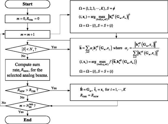
Flow chart for our proposed low-complexity analog beam selection algorithm
Let us denote the weighted effective channel over the users whose analog beams are determined, \(\bar {\mathbf {h}}\), as
$$ \bar{\mathbf{h}}=\sum_{j\in S}\alpha_{j}\mathbf{h}_{j}^{\text{eff}}\left(\mathbf{G}_{m},\mathbf{x}_{j}\right), $$(29)where \( \alpha _{j}=\left \|\mathbf {h}_{j}^{\text {eff}}\left (\mathbf {G}_{m},\mathbf {x}_{j}\right)\right \|^{2}/\sum _{j\in S}\mathbf {h}_{j}^{\text {eff}}\left (\mathbf {G}_{m},\mathbf {x}_{j}\right)\) is the weighted factor for the jth user whose analog beam is chosen as x j . The analog beams for the rest K−1 users whose analog beams are not determined are selected by measuring the orthogonality between “the effective channels of the users whose analog beams are not chosen” and “the weighted effective channel over the users whose analog beams are determined.” Then, it can be formulated as
$$ (i,\mathbf{x}_{i})=\arg\max_{\left(k\in\Omega,\mathbf{c}_{n}\in\mathcal{C}\right)} f\left(\bar{\mathbf{h}},\mathbf{h}_{k}^{\text{eff}}\left(\mathbf{G}_{m},\mathbf{c}_{n}\right) \right). $$(30)After the analog beams for all users are chosen, we can calculate the sum rate.
-
(2)
Determination of the analog beams: We obtain the sum rate values for the predefined \(N_{\text {BS}}^{\text {BSS}}\) analog beams by executing (1). Then, by comparing the sum rate values for each of receive analog beams, we decide the analog beams for both BS and users which provide the maximum sum rate.

As we can see, the proposed analog beam selection algorithm does not need to search over all possible analog beams, which can reduce the complexity compared to the optimum analog beam selection while the loss of sum rate performance is not significant.
5.3 Complexity analysis
In this subsection, we compare the complexity of the proposed analog beam selection algorithm with the exhaustive search in terms of the required number of floating point flops [23]. For mathematical convenience, the complexities to calculate the sum rate and the metric in (27) for the selected analog beams of BS and users are set to α and β, respectively. The complexity for our proposed analog beam selection algorithm is summarized as follows.
-
1.
We first quantify the complexity to select the transmit analog beams of the users and calculate the sum rate value when the receive analog beam at BS is fixed.
-
Calculating Forbenius norm of the estimated channel requires 4N s floating point flops. Since there are K users and each user has \(N_{\text {user}}^{\text {BSS}}\) possible analog beams, we need to consider \(KN_{\text {user}}^{\text {BSS}}\) effective channels to find the first user and select its analog beam which provides the maximum vector norm among \(KN_{\text {user}}^{\text {BSS}}\) effective channels, which requires \(4 N_{\mathrm {s}}KN_{\text {user}}^{\text {BSS}}\) flops.
-
Since the analog beams for the other K−1 users are selected by using the metric in (27), the number of flops to select the analog beams for the other K−1 users is \((N-1)N_{\text {user}}^{\text {BSS}}\beta +(N-2)N_{\text {user}}^{\text {BSS}}\beta +\cdots +N_{\text {user}}^{\text {BSS}}\beta =\frac {\left (K-1\right)K}{2}N_{\text {user}}^{\text {BSS}}\beta \).
-
Therefore, when the receive analog beam at BS is fixed, the complexity to select the transmit analog beams of the users and calculate the sum rate value is \(N_{\mathrm {s}}KN_{\text {user}}^{\text {BSS}}+\frac {\left (K-1\right)K}{2}N_{\text {user}}^{\text {BSS}}\beta +\alpha \).
-
-
2.
Since BS selects the analog beam which provides the maximum sum rate value among the sum rate values for \(N_{\text {BS}}^{\text {BSS}}\) possible receive analog beam, the complexity for the proposed low-complexity analog beam selection algorithm is estimated as
$$ \mathcal{O} \left(N_{\text{BS}}^{\text{BSS}}\left(4 N_{\mathrm{s}}KN_{\text{user}}^{\text{BSS}}+\frac{\left(K-1\right)K}{2}N_{\text{user}}^{\text{BSS}}\beta+\alpha\right)\right). $$(31)
For the exhaustive search, we need to calculate the sum rate of all possible combinations and select the analog beams which provide the maximum sum rate. Therefore, the complexity of the exhaustive search is given by
From (31) and (32), we can observe that the proposed analog beam selection algorithm has much lower complexity compared to the exhaustive search. Although we can intuitively notice that α is larger than β, in order to more precisely compare the complexity, we implement both the proposed analog beam selection algorithm and exhaustive search based on MATLAB. Figure 5 gives a comparison of average running time for the proposed analog beam selection algorithm and exhaustive search with a case of [(4,6,24),(4,2)] and \(N_{\text {user}}^{\text {BSS}}=6\) on MATLAB. We can see that the average running time of the proposed analog beam selection algorithm is less than that of the exhaustive search. Especially, the gap of running time between the proposed analog beam selection algorithm and exhaustive search becomes much larger as the cardinality of analog beam set for BS increases. Therefore, the proposed analog beam selection algorithm is computationally more efficient.

Average running time of MATLAB codes
5.4 Procedure for analog beam selection
The most important part to operate the proposed analog beam selection algorithm is to acquire the channel information by using the proposed channel estimation methods according to the kind of channel model. The outline of procedure for the proposed analog beam selection algorithm is outlined as follows:
-
Step 1: The users transmit the multiple pilot sequences so that BS can obtain the effective channel information.
-
Step 2: BS estimates the effective channels of the users by using the proposed channel estimation methods in Section 4.
-
Step 3: With the obtained effective channels, BS selects the analog beams for both BS and users by using the proposed analog beam selection algorithm.
-
Step 4: BS feeds back the indices of the analog beams for the users via error-free feedback link.
6 Numerical results
In this section, we present simulation results to validate the proposed channel estimation methods and low-complexity analog beam selection algorithm. We consider Rayleigh fading and ULA channel models. The proposed different channel estimation methods are applied according to the kind of channel model. Throughout simulations, we consider the uplink multiuser hybrid beamforming system with a case of [(4,6,24),(4,2)]. The signal-to-noise ratio (SNR) is defiend as \(\frac {P}{\sigma ^{2}}\). The ULA channel environment is assumed to have L=5 scatters with uniformly random angle of arrival and departure. The complex path gains of ULA channel model are generated using Gaussian random distribution with equal variance. The inter-element spacing in both BS and user antenna arrays is set to half a wavelength. The phase of each entry in the predefined analog beams is generated using a random variable distributed uniformly between 0 and 2π. The covariance value of AWGN is 1 per entry. We consider the exhaustive search under the perfect channel knowledge as a benchmark, which is the optimum solution, and the random beam selection, which randomly selects the analog beams among the predefined analog beams, as a baseline algorithm for comparison with our proposed analog beam selection algorithm.
In Fig. 6, we plot the average sum rate as a function of SNR with \(N_{\text {BS}}^{\text {BSS}}=16\) and \(N_{\text {user}}^{\text {BSS}}=4\). Figure 6 shows that the proposed analog beam selection algorithm achieves the sum rate that is essentially equal to those achieved by the exhaustive search. This implies that the proposed analog beam selection algorithm has little performance degradation in spite of much less complexity than the exhaustive search under the equal system configuration. For instance, the proposed analog beam selection algorithm provides only 1.20 % sum rate performance reduction over the exhaustive search in ULA chanel when SNR =20 dB.

Comparison of sum rate performance according to the value of SNR. a Rayleigh fading channel. b ULA channel
Figure 7 depicts the average sum rate versus the cardinality of analog beam set for BS when \(N_{\text {user}}^{\text {BSS}}=4\). It is noticed that the sum rate performance with the analog beam selection can be improved as the cardinality of analog beam set for BS increases, which indicates that the analog beam selection has great impact on the system performance. Also, Fig. 7 indicates that similar performance can be expected by the proposed analog beam selection algorithm and that the performance degradation due to the reduction of the complexity is limited, especially when the cardinality of predefined analog set is large.

Comparison of sum rate performance according to the cardinality of analog beam set for BS when \(N_{\text {user}}^{\text {BSS}}=4\). a Rayleigh fading channel. b ULA channel
From Figs. 5 and 7, we can notice that the performance loss of the proposed analog beam selection algorithm is not significant compared to the optimum analog beam selection while the proposed analog beam selection algorithm has much less complexity than the exhaustive search based optimum analog beam selection. Therefore, the proposed analog beam selection algorithm is more efficient to be realized on the uplink multiuser hybrid beamforming system.
7 Conclusions
In this paper, we considered an uplink multiuser hybrid beamforming system and investigated the design of channel estimation and analog beam selection algorithm. First, we not only developed the channel estimation method for Rayleigh fading which exploits the full channel information over multiple pilot periods by obtaining the partial channel knowledge during one pilot period and but also considered the channel estimation method for mmWave channel model. Then, we proposed the analog beam selection algorithm for the uplink multiuser hybrid beamforming system that efficiently reduces the complexity over the optimum analog beam selection algorithm. Based on the metric derived from the sum rate performance analysis of the uplink two-user hybrid beamforming system, the proposed analog beam selection algorithm selects the analog beams for both BS and users. By analyzing the complexity in terms of flops, we showed that the proposed analog beam selection algorithm provides much less complexity than the optimum analog beam selection algorithm. We verified by numerical results that the proposed analog beam selection algorithm has little performance degradation in spite of much less complexity than the optimum analog beam selection algorithm under the equal system configuration.
References
D Tse, P Viswanath, Fundamentals of Wireless Communication (Cambridge University Press, Cambridge, 2005).
3GPP Physical Channels and Modulation, TS 36.211 (release 10) (2009).
IEEE Std 802.11ac, Wireless LAN medium access control (MAC) and physical layer (PHY) specifications–amendment 4: enhancements for very high throughput for operation in bands below 6 GHz (2013).
F Rusek, D Persson, BK Lau, EG Larsson, TL Marzetta, O Edfors, F Tufvesson, Scaling up MIMO: opportunities and challenges with very large arrays. IEEE Signal Process. Mag. 30(1), 40–60 (2013).
J Hoydis, S ten Brink, M Debbah, in Proceedings of 2011 49th Annual Allerton Conference on Communication, Control, and Computing. Massive MIMO: How many antennas do we need? (IL, USA, 2011), pp. 545–550.
HQ Ngo, EG Larsson, TL Marzetta, Energy and spectral efficiency of very large multiuser MIMO systems. IEEE Trans. Commun. 61(4), 1436–1449 (2013).
F Rusek, D Persson, BK Lau, EG Larsson, TL Marzetta, O Edfors, F Tufvesson, Scaling up MIMO: opportunities and challenges with very large arrays. IEEE Signal Process. Mag. 30(1), 40–60 (2013). doi:10.1109/MSP.2011.2178495.
RC de Lamare, Massive MIMO systems: signal processing challenges and future trends. Union Radio-Scientifique Internationale (URSI) Bulletin (2013).
TL Marzetta, Noncooperative cellular wireless with unlimited numbers of base station antennas. IEEE Trans. Wireless Commun. 9(11), 3590–3600 (2010).
F Gholam, J Via, I Santamaria, Beamforming design for simplified analog antenna combining architectures. IEEE Trans. Veh. Technol. 60(5), 2373–2378 (2011).
International Telecommunication Union-Radiocommunication (ITU-R), in Tech. Rep., ITU-R M.2243. Accessment of the global mobile broadband deployments and forecast for international mobile telecommunications.
Z Pi, F Khan, An introduction to millimeter-wave mobile broadband systems. IEEE Commun. Mag. 49(6), 101–107 (2011).
IEEE 802.11ad standard draft D0.1. [Online] (2013), Available: www.ieee802.org/11/Reports/tgadupdate.htm.
Standard ECMA-387, High rate 60 GHz PHY, MAC and HDMI PAL. [Online] (2009), Available: http://www.ecma-international.org/.
S Sun, TS Rappaport, RW Heath, A Nix, S Rangan, MIMO for millimeter-wave wireless communications: beamforming, spatial multiplexing, or both?IEEE Commun. Mag. 52(12), 110–121 (2014). doi:10.1109/MCOM.2014.6979962.
S Hur, T Kim, DJ Love, JV Krogmeier, TA Thomas, A Ghosh, Millimeter wave beamforming for wireless backhaul and access in small cell networks. IEEE Trans. Commun. 61(10), 4391–4403 (2013).
J Wang, Z Lan, C-W Pyo, T Baykas, C-S Sum, MA Rahman, J Gao, R Funada, F Kojima, H Harada, S Kato, Beam codebook based beamforming protocol for multi-GBPS millimeter-wave WPAN systems. IEEE J. Sel. Areas Commun. 27(8), 1390–1399 (2009).
YM Tsang, ASY Poon, S Addepalli, in Proceedings of IEEE GLOBECOM 2011. Coding the beams: improving beamforming training in mmWave communication system (Houston, Texas, USA, 2011), pp. 1–6.
X Zhang, AF Molisch, S-Y Kung, Variable-phase-shift-based RF-baseband codesign for MIMO antenna selection. IEEE Trans. Signal Process. 53(11), 4091–4103 (2005).
V Venkateswaran, A-J van der Veen, Analog beamforming in MIMO communications with phase shift networks and online channel estimation. IEEE Trans. Signal Process. 58(8), 4131–4143 (2010).
QH Spencer, BD Jeffs, MA Jensen, AL Swindlehurst, Modeling the statistical time and angle of arrival characteristics of an indoor multipath channel. IEEE J. Sel. Areas Commun. 18(3), 347–360 (2000).
O El Ayach, S Rajagopal, S Abu-Surra, Z Pi, RW Heath, Spatially sparse precoding in millimeter wave MIMO systems. IEEE Trans. Wireless Commun. 13(3), 1499–1513 (2014).
GH Golub, CF Van Loan, Matrix Computations, vol. 3 (JHU Press, Baltimore, 2012).
Acknowledgements
This work was supported in part by ICT R&D program of MSIP/IITP [2014-044-006-004, Next Generation WLAN System with High Efficient Performance].
Author information
Authors and Affiliations
Corresponding author
Additional information
Competing interests
The authors declare that they have no competing interests.
Rights and permissions
Open Access This article is distributed under the terms of the Creative Commons Attribution 4.0 International License(http://creativecommons.org/licenses/by/4.0/), which permits unrestricted use, distribution, and reproduction in any medium, provided you give appropriate credit to the original author(s) and the source, provide a link to the Creative Commons license, and indicate if changes were made.
About this article

Cite this article
Ko, YC., Kim, MJ. Channel estimation and analog beam selection for uplink multiuser hybrid beamforming system. J Wireless Com Network 2016, 155 (2016). https://doi.org/10.1186/s13638-016-0618-0
Received:
Accepted:
Published:
DOI: https://doi.org/10.1186/s13638-016-0618-0