- Research
- Open access
- Published:
Modelling and implementation of virtual radio resources management for 5G Cloud RAN
EURASIP Journal on Wireless Communications and Networking volume 2017, Article number: 128 (2017)
Abstract
The virtualisation of Radio Access Networks (RANs) is one of the goals in designing 5G mobile networks. This paper aims at presenting a proof of concept for the virtualisation of radio resources using Open Air Interface (OAI), a software-based Long-Term Evolution (LTE) eNodeB physical emulator. OAI was extended to support multi-tenancy, representing diverse Virtual mobile Network Operators (VNOs) with different Service Level Agreements (SLAs). A comprehensive analytical model for managing the virtual radio resources has been proposed, with two key parts: estimation of available radio resources and their allocation to different VNOs. The estimation is performed by the model, and the allocation is managed by OAI scheduling. Various scenarios and use cases are studied in this virtual RAN environment, network performance being evaluated for different situations, by varying guaranteed levels, serving weights, and used services. Results show that the proposed approach offers almost the same capacity to guaranteed VNOs regardless of other existing VNOs, experiencing at worst a degradation of 32% of its initial allocated data rate, without violation of the guaranteed data rate. The data rate allocated to best effort VNOs may decrease up to 7% of its initial value, which is acceptable, to guarantee other more demanding SLAs.
1 Introduction
Future mobile networks will face an even faster growth of mobile data demand [1]. Nevertheless, drastic temporal and geographical variations of traffic, in addition to the shortage of network capacity, put a very challenging situation to operators [2]. The common provisioning approach used in Radio Access Networks (RANs) of considering only busy hours is no longer acceptable. It leads to an inefficient resource usage with high CAPital and OPerational Expenditures (CAPEX and OPEX, respectively) costs. Thus, operators have to find a practical, flexible, and cost-efficient solution for their networks, in order to address this issue, as they have scarce radio resources available. On the other hand, the appearance of Virtual Network Operators (VNOs), which aim to provide specific services without owning an infrastructure can be seen as a definitive trend. The combination of these two challenges lead to the motivation of the current paper, addressing the need of an efficient management of varying radio resources shared among multiple VNOs, guaranteeing agreed Service Level Agreements (SLAs).
The design of a future Internet architecture favours multiple coexisting solutions, designed and customised to satisfy specific network requirements, rather than trying to achieve a global architecture that fits all [3]. A network environment with multiple virtual networks coexisting on the same physical infrastructure is supported by the concept of network virtualisation [4]. Regardless of the wired or wireless nature of networks, virtualisation can be considered as the process of splitting the entire network into multiple concurrent ones, non-transparent to each other [5]. In this sense, the virtualisation of wireless networks is considered as a technology in which the physical network infrastructure and its radio resources are abstracted and sliced into virtual wireless network resources. These can then be shared among multiple parties, while holding isolation in addition to the other functionalities [6, 7].
The virtualisation of RAN has been addressed in recent studies [8]. In particular, virtualisation strategies for 5G in advanced computational platforms, such as cloud computing, have been presented [9]. The advantages of these so-called Virtual RANs (V-RANs) can be summarised as follows:
-
Elimination of cell boundaries [10, 11]: in contrast to traditional solutions, the network determines which Base Stations (BSs) the Mobile Terminal (MT) is associated with, in order to provide a centre-cell experience throughout the entire network, so that the MT does not experience a degradation of link performance as it moves away from the BS.
-
Isolation among virtual instances [7, 12, 13]: the isolation among VNO instances ensures that traffic and mobility, in addition to the fluctuations in the channel conditions of MTs, do not affect the Quality of Service (QoS) offered to other VNOs. It also enables multiple VNOs, with different objectives and requirements, to operate in the same physical infrastructure. Achieving a lower downtime is another advantage of having isolation among VNOs.
-
Flexibility [14], programmability [15], and customisation of virtual networks [16]: they enable an easier and faster evaluation of the new proposed networking technologies, without considering the complicated interfaces and characteristics of physical infrastructures.
-
Multi-Radio Access Technologies (Multi-RAT) support [15, 17]: offloading of traffic (e.g., to Wi-Fi) cannot be realised for multiple VNOs operating over the same physical infrastructure, since there may not be enough channels to separately allocate a set to each VNO [18]. The solution is to virtualise radio resources to implement a Wi-Fi virtual link for each VNO.
The virtualisation of wireless networks has proven to be an active research topic. The management of resources (e.g., radio, fibre, and processing resources) is the focus of many works [19], since the performance of virtual wireless networks is strongly affected by the way resources are used [20, 21]. Aiming at achieving an efficient mapping from virtual radio resources onto available physical ones, a negotiation-based approach focusing on Long-Term Evolution (LTE)-Advanced is proposed in [22]. The authors in [23] propose a technique that uses MT-centric metrics to provide multiple partitions of a wireless network into virtual transmission point sets. A dynamic cloud resource sharing scheme of processing resources, based on the Indian buffet game, is presented in [24]. A service-aware user-centric resource allocation scheme is presented in [25], which achieves multi-point fairness in downlink. Regarding radio resources, various studies considered various forms of spectrum sharing [8, 26, 27]. The authors in [28] presented a solution, in addition to a demo, for the virtualisation of wireless local networks. The modelling of the Virtual Radio Resource Management (VRRM) for cellular heterogeneous access networks is presented in [29,30,31]. The key idea is to aggregate and manage all the physical radio resources, to create virtual wireless links, and to offer Capacity-as-a-Service.
The novelty of this paper is to present, for 5G C-RAN, a proof of concept of the VRRM model using the Open Air Interface (OAI) [32], an open-source software-based implementation of LTE, spanning the full protocol stack both in E-UTRAN and EPC [33]. To achieve it, OAI is extended to support multi-tenancy, representing diverse VNOs with different SLAs. The estimation is performed by the model, and the allocation is managed by OAI scheduling. A specific scenario of usage is considered to demonstrate the performance of the VRRM model. The key principle that is demonstrated is the capability of the VRRM algorithm to interact with the scheduling algorithm in order to guarantee the specific SLAs of different VNOs, which is independent of the selected frequency bands and service profiles. In this sense, this concept can be applied to other frequency bands and types of services.
The rest of this paper is organised as follows. Section 2 presents the architecture of V-RAN. The concept of virtualisation of radio resources, and the used analytical model, is briefly addressed in Section 3. Section 4 introduces the architecture used for integration, followed by the algorithms for integration in Section 5. The reference scenario, use cases, and scenario variations, based on which numeric results were obtained, are introduced in Section 6. The analysis of results is discussed in Section 7. Finally, the conclusions are drawn in Section 8.
2 Architecture
The V-RAN architecture has been considered as the reference architecture for the integration of VRRM in OAI, encompassing the virtualisation of radio resources based on C-RAN [2]. Although the V-RAN architecture envisages the existence of diverse RATs, in order to meet the main objective of integration and demonstration, OAI has been chosen to build and customise an LTE BS and connected Users Equipment (UEs), in order to test different configurations and network setups and to monitor the network and MTs in real time.
The reference architecture is depicted in Fig. 1, its key architectural elements being:
-
VNOs: network operators that do not own a RAN infrastructure, asking the V-RAN enabler for connectivity in terms of capacity to carry various services traffic with various QoS requirements to/from their subscribers.
-
Backhaul transport network: a low latency optical transport network, which connects the operators’ cores to the physical infrastructure of a RAN.
-
Virtualisation platform: the key difference between a C-RAN and a V-RAN. On the one hand, it is in charge of abstracting the physical infrastructure for the VNOs, while on the other hand, it handles the request of VNOs through the available physical resources. The most important functionality of the virtualisation platform is the VRRM, the highest manager, which is in charge of translating VNO requirements and SLAs through sets of polices onto the lower levels. It optimises the usage of virtual radio resources, without dealing with the management of the physical ones. Reports and monitoring information (e.g., estimated remained capacity) received from lower levels enables it to improve policies.
-
Base Band Unit pools (BBU-pools) data centre: a set of Virtual Machines used for baseband processing of traffic among UEs and network cores.
-
Fronthaul transport network: it carries signals between BBU pools and Remote Radio Heads (RRHs), using Common Public Radio Interfaces, with high data rates over optical fibres. The optical equipment needs to have the lowest delay possible, since the maximum round-trip delay must be below 150 μs (i.e. a maximum of 15 km of BBU-RRH distance) [34]. The optical switch must enable the scaling or migration of BBU pools in multiple data centres.
-
RRHs: transceivers in charge of exchanging data and control traffic to/from UEs through the air interface, supporting multiple RATs.
Fig. 1 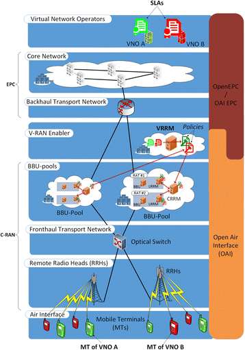
Architecture of a V-RAN

By comparing C-RANs with current mobile networks, it can be seen that the BS has been divided into RRHs and BBU pools (and the transmission in between them). The virtualisation platform, which offers isolation, element abstraction, and multi-tenancy, does not exist in current networks. The changes in the architecture and the dedicated hardware replacement by Virtual Machines in data centres provide high flexibility, resource efficiency, and cost reduction.
By crossing the V-RAN architecture with the OAI wireless technology platform, one can identify the last three elements as possibly being implemented by the OAI BSs. VNOs, on the other hand, can deploy their own Open EPCs, which can be implemented by OAI EPCs.
3 Virtualisation of radio resources
3.1 Initial considerations
The concept of virtualisation of radio resources to achieve virtual wireless links, as the milestone in the realisation of end-to-end virtual networks, is presented in [29]. The proposed concept is based on the aggregation of all physical radio resources from different RATs, in order to offer VNOs on-demand, flexible, and efficient wireless connectivity. In this novel methodology, VNOs ask for wireless capacity from a set of RAN Providers to serve their subscribers, without having to deal with the physical infrastructure at all. RAN Providers, owning the physical infrastructure, are capable of offering Capacity-as-a-Service to VNOs. The advantages of RAN virtualisation compared to RAN sharing (where each operator is allocated a portion of spectrum) come from network element abstraction, isolation among virtual instances, and the ability to support multi-RATs and new business models.
The management of virtual radio resources is a complex optimisation problem, since network status and constraints vary in time. Among various possible techniques and approaches for solving this problem, partial VRRM seems to be the simplest one [30], where the main optimisation problem is broken into multiple sub-problems; in other words, the time axis is divided into decision windows, and VRRM maximises the objective function in each of these intervals, independently. However, it is worthwhile noticing that decisions in each interval affect the network state directly, and the outcome at a certain interval depends on the states in previous ones, the optimal solution needing to consider this dependency. Therefore, the output of partial VRRM is a local minimum and not the global one; nevertheless, partial VRRM is a simple solution, which can be used as the starting step and a reference point.
3.2 Estimation of available resources
In general, the data rate of a Radio Resource Unit (RRU) (e.g. timeslot in GSM, code in UMTS, and resource block in LTE), assigned to a UE, varies between 0 and a maximum value. This depends on various parameters, such as the RAT, modulation, and coding schemes; thus, it can be given as a function of channel quality, i.e. Signal to Interference plus Noise Ratio (SINR).
The estimation of available resources is made by VRRM, based on the model presented in [29] and the approaches presented in [35]. In this model, the network is modelled as a K-tier network, where each tier models the BSs of a particular class. It is assumed that the BSs in a given tier are spatially distributed as a Poisson Point Process with a given density and transmission power. The received power is assumed to be exponentially distributed (i.e. Rayleigh fading is assumed for the signal magnitude). Based on the data rates of different access technologies as a function of SINR, and the distribution of SINR, the Probability Density Function (PDF) of a single RRU of each RAT is calculated.
The PDF of the total date of a single RAT (assuming that channels are independent [36]), is equal to the convolution of all RRUs’ PDFs. Likewise, the PDF of the total network data rate is computed by convolving all RATs’ PDFs. By obtaining the total network PDF and Cumulative Density Function (CDF), an estimation of the available network capacity is in hand to be used in the allocation procedure.
3.3 Allocation of radio resources
After estimating the total network capacity, the VRRM has to distribute it among the various network services. The key objective, in the allocation of resources, is to maximise the usage efficiency, by taking restrictions into account, e.g. priority of services to different VNOs based on their SLAs.
SLAs can generally be categorised into three types:
-
Guaranteed Bitrate (GB) guarantees minimum and maximum data rates, regardless of the network status. The total satisfaction of the VNO is achieved when the maximum guaranteed data rate is allocated to it. The upper boundary enables VNOs to have full control of their networks, e.g. a VNO may decide to offer VoIP to only 30% of its subscribers simultaneously, which can put into practice by choosing a guaranteed SLA for its VoIP service. It is expected that subscribers always experience a good QoS in return of relatively more expensive services.
-
Best effort with minimum Guaranteed (BG) guarantees a minimum level of service (i.e. data rate), but the request for data rates higher than the guaranteed one is served in a best effort manner. In this case, although VNOs do not invest as much as former ones, they can still guarantee the minimum QoS to their subscribers. From the subscribers’ viewpoint, the acceptable service (not as good as the previous ones) is offered with a relatively lower cost.
-
Best Effort (BE), in which the VNO is served in a pure best effort way. Operators, and consequently their subscribers, in return, may suffer from low QoS and resource starvation during busy hours.
The allocation of radio resources is based on one objective function, presented in [30], where a set of weights are used to prioritise the allocation of data rates to the different services of the different VNOs: services with higher weights are served with higher data rates. The choice of these weights is based on the SLAs between the VNOs and VRRM; hence, the objective function for VRRM can be written as follows:
where
-
\( {f}_{{\mathbf{R}}_{\mathbf{b}}}^{cell} \): objective function for cellular RATs
-
\( {\mathbf{R}}_{\mathbf{b}}^{\mathbf{cell}} \): vector of serving data rates from cellular networks,
-
\( {f}_{{\mathbf{R}}_{\mathbf{b}}}^{WLAN} \): objective function for WLANs
-
\( {\mathbf{R}}_{\mathbf{b}}^{\mathbf{WLAN}} \): vector of serving data rates from WLANs
-
\( {f}_{{\mathbf{R}}_{\mathbf{b}}}^f \): fairness function
-
\( {\mathbf{R}}_{\mathbf{b}}^{\mathbf{f}} \): vector of intermediate fairness variables
-
\( {\mathbf{R}}_{\mathbf{b}}^{\mathbf{Srv}} \): vector of serving data rates
The objective function for cellular RATs in (1) is given by
where
-
N VNO : number of served VNOs in the VRRM
-
N srv : number of services for each VNO
-
\( {W}_{ji}^{Srv} \): weight of serving unit of data rate for service j of VNO i, where \( {W}_{ji}^{Srv}\in \left[0,1\right] \)
The objective function for WLANs in (1), where the goal is to minimise the collision rates, is given by
where
-
W SRb: weight for session average data rate, where W SRb ∈ [0, 1]
-
\( \overline{R_b^{max}} \): maximum average data rate among all network services
-
\( \overline{R_{b_j}} \): average data rate for service j
There are also constraints in the allocation of data rates that should not be violated. The fundamental constraint is the estimated total network capacity, in addition to minimum and maximum guaranteed data rates.
In the allocation process, there may be situations where resources are not enough to meet all guaranteed capacity, the optimised allocation being no longer feasible. In these cases, constraints are relaxed by the introduction of a violation (also known as slack) parameter and weights, with which the former infeasible optimisation problem turns into a feasible one, where the optimal solution maximises the objective function and minimises the weighted average constraints violations.
The received VRRM policies and associated data rates must be translated into a specific number of RRUs for each VNO. This mapping occurs at the Local RRM level, being based on the average Modulation and Coding Scheme (MCS) received in the monitoring reports. The translation function pre-allocates the required RRUs, from the available ones of each VNO, to achieve the data rates dictated by the policies.
4 Integration overview
The infrastructure to implement the concept of virtualisation of radio resources is a cloud host environment of servers.
OAI [32] is an open-source software-based LTE eNodeB, enabling the integration and implementation of these concepts. The transceiver functionality is realised by a software radio front end, connected to a host computer for processing. OAI enables to build an open cellular ecosystem for flexible and low-cost 5G deployment and experimentations with the following characteristics:
-
Open and integrated development environment under the control of experimenters.
-
Fully software-based network functions offering flexibility to architect, instantiate, and reconfigure network components (at the edge, core, or cloud, using the same or different addressing space).
-
Playground for commercial handsets, as well as application, service, and content providers.
-
Rapid prototyping of 3GPP compliant and non-compliant use cases, and new concepts towards 5G, from Machine-to-Machine/Internet of Things (M2M/IoT) and Software-Defined Network (SDN) to Cloud-RAN (C-RAN) and massive Multiple Input Multiple Output (MIMO).
OAI is implemented in Linux, using a cellular network emulator [32], while VRRM is implemented in a Windows-based server, deployed on the same network domain, as depicted in Fig. 1. The VRRM server issues policies based on information and statistics received from the infrastructure emulator. The servers are connected through an internal network, managed by the cloud provider, the links carrying information and control signals among servers. A bidirectional interface between OAI and VRRM using Transmission Control Protocol (TCP) sockets was defined to:
-
Transfer scenarios and configurations from OAI to VRRM.
-
Send policies from VRRM to OAI.
-
Retrieve real-time statistics and information of VNOs from OAI for VRRM.
In order to support VRRM policies, the OAI scheduler required modifications to differentiate groups of subscribers, one per VNO. With this approach, it is possible to impose different policies per VNO/group, offering different levels of QoS to UEs according to the VNO/group they belong to. By collecting operation statistics separately per VNO/group, the scheduler may adapt to meet the diverse requirements. The following modifications on OAI were implemented:
-
Adding group-based statistics to an eNodeB
-
Introducing new sets of long-time statistics, using the already implemented listing concept
-
Changing the codes to initialise, fill, and use the aforementioned statistics
-
Changing the MAC scheduler algorithm in order to support the groups’ policies
-
Adding support for bidirectional connections and the required protocols
-
Changing the codes to add the groups’ information into the XML file.
5 Algorithms for integration
5.1 VRRM server
5.1.1 Module structure
Figure 2 presents the flowchart of the VRRM server. Before the appearance of the Graphical User Interface on screen, there are multiple initialisations to be done. At first, the server makes a connection to the SQL Server [6]. The database is used to speed up the procedure by not re-calculating intermediate steps or results. Considering the VRRM procedure in specific, calculating the PDFs of RRUs, RATs, and network is the most time-consuming tasks during evaluations and simulations. By saving the intermediate results during the calculation of probability functions, it is possible to significantly decrease the processing time.

VRRM module flowchart
Afterwards, the optimisation module is initialised. The optimisation function was developed in MATLAB [37] and converted to a managed Dynamic Library Link (DLL); the optimisation is based on the interior-point method, using MATLAB’s linprog [29]. The initialisation of MATLAB-based modules is more time-consuming than other elements; hence, the initialisation is done once at the beginning and used multiple times later on. After having all the pre-requisite modules loaded, the control panel appears.
5.1.2 Communication with OAI
In order to enable the integration of VRRM with OAI, a pre-defined scenario, designated by OAI Integration, has been included (Fig. 3).

VRRM module flowchart for OAI integration
After loading the real-time charts, the TCPLink module starts, and the user is asked to choose the right interface for communicating with the OAI server. A waiting form is shown, informing the VRRM server is waiting for receiving the packet event from OAI, meaning the connection has been established. VRRM listens over these links for scenario description and reports, which also uses to send policies to OAI.
Upon reception of a new message by VRRM, it checks for the “Scenario Description” message; then, the message is parsed and the scenario details are extracted. In the next step, the RAT module that contains the properties of the radio resources is created and initialised. After initialising the CRRM and VRRM modules, the VNOs based on the received scenario are formed. Finally, the services are added to the VNOs.
In the next stage, the VRRM model optimisation is solved, results are produced, and the new policy flag is set.
5.2 OAI extensions to support multiple VNO
5.2.1 Module structure
In addition to the development of the VRRM server, OAI also needs some adaptation to support multiple VNOs or groups operating in the same infrastructure. A key requirement is to gather the statistics per VNO/group, instead of all UEs.
OAI stores UEs’ key performance indicators, e.g. total data rates offered to the UEs in downlink. The following group-based statistics have been added to OAI, per sub-frame: MAC Protocol Data Units (PDUs), transferred size, download data rate, MCS, and active/scheduled UEs.
These statistics are used in the scheduler for enforcing the VRRM’s generated policies and management of radio resources. The reports for the VRRM server contain statistics over an observation window, which may be as long as the decision window discussed in VRRM modelling [30]. In order to calculate the long-term behaviour, the statistics obtained in each sub-frame are collected by using the already implemented listing concept in OAI. The following group of variables’ list was added: bitrate, MCS, and active/scheduled UEs.
These variables have to be initialised during the eNodeB MAC initialisation phase. Figure 4 shows the flowchart for collecting, calculating, and reporting the long-term statistics. As the VNO statistics become available in each sub-frame, they are pushed into the corresponding lists. At the end of each sub-frame, a counter is placed to acknowledge the number of sub-frames. When the counter’s value becomes equal to the length of the observation window, the average of the aforementioned statistics pushed into the lists is calculated for the observation interval, and reported to the VRRM server, using the Real-Time Report message. Finally, lists are cleared, and the sub-frame counter is set to 0.

Flowchart of calculating and reporting long-term statistics
5.2.2 Changing the algorithm of MAC scheduler in order to support the groups’ policies
The key methods implemented in OAI’s downlink scheduler are pre-allocation and allocation (Fig. 5). The former aims at storing the UEs’ Downlink–Shared Chanel (DL-SCH) buffer, and calculating the number of required RBs per UE, while in the latter, RBs are effectively allocated to UEs.

Flowchart of downlink scheduler
In the following, the changes introduced to this function to support multiple VNOs/groups are described. Some modifications were introduced in the UEs’ sorting function. Originally, UEs were sorted based on the following aspects:
-
HARQ round: users that are in their second round of HARQ are given higher priority.
-
Bytes in the buffer: users that have more bytes to receive are moved to the beginning of the user list.
-
Maximum time of SDU creation: users with more delay tolerance are pushed to the back of list, opening up space for other users.
-
UE ID: in the case all the other criteria match, the UE ID is the last sorting criterion.
This function was changed in order to put users of higher priority VNOs on the top of the list, before checking the other criteria. Based on the policies received from VRRM, each VNO receives a portion of available RBs, the goal being to start the user list with the users of VNOs with the biggest share of RBs. The flowchart for sorting UEs is depicted in Fig. 6.

UE sorting algorithms
The pre-allocation sequence is modified to support the possibility of having multiple VNOs/groups with different priorities. The pre-allocation was implemented initially as it is shown in Fig. 7, without the blue boxes. When there are scheduled UEs, the RBs required to fully serve each of them are calculated; then, the possibility of allocating at least a minimum RB units (i.e. two RBs in the implementation of OAI) to all the scheduled UEs is checked. The minimum RB units are pre-allocated to all scheduled UEs when there are not enough resources; otherwise, the average RB per UE obtained in the last step is pre-allocated.

Pre-allocation procedure
Then, based on the sorted UE list, each terminal that has to receive the control information is granted with the required RBs. Regarding data traffic, all UEs are pre-allocated the average RBs, unless the required RBs for a user is smaller than the average RBs, in which case the UE is pre-assigned only the required RBs.
In order to add multi-tenancy, the pre-allocation procedure is changed by calling a new function that maps the assigned data rate of each VNO onto its share of available resources, the blue boxes in Fig. 7. For each frame, the sharing of available resources is updated, based on the policies received from VRRM, minimum data rate for each VNO, and key performance indicators, namely, the average MCS per VNO.
The number of RBs per VNO is calculated by dividing the assigned minimum data rate by the average achieved MCS. The adaptation to the maximum number of RBs available for the eNodeB is considered in a second step, in order to avoid overbooking.
Then, the same pre-allocation procedure is done, but this time only per VNO, i.e. the average RBs per VNO is calculated, and used instead of the average RB in the previous approach. The flowchart of the pre-allocation procedure with the new algorithm is illustrated in Fig. 7. It is worthwhile noting that the primary goal was to implement the support for virtualisation of radio resources with minimum changes in OAI.
5.2.3 Changing the codes to add the group information into the input XML file
In order to input the group information, a new set of parameters identified by <PROTOCOL><MAC> tags were added to the input XML file. In the <VRRM> section, the parameters for the TCP/IP communication are defined, namely, the IP address of the machine in which VRRM is running and the TCP port. The VRRM_LINK parameter allows running OAI without the connection to VRRM, but maintaining the virtualisation of radio resources for serving different VNOs.
In the following lines, the number of VNOs/groups and the quantity of frames that are considered for each report sent to VRRM are set. Finally, in the <GROUPS> section, the statistic information for each group is stated. The three previously defined SLAs are considered: BE, BG, and GB; the differentiation among these groups is based on the data rate assigned to GROUP_MIN_GB and GROUP_MAX_GB (Table 1 ). The SERVICE_WEIGHT and VIOLATION_WEIGHT are parameters used for the optimisation performed by VRRM module, allowing distinguishing among VNOs of the same type.
5.2.4 Adding support for bidirectional connection and protocols
The communication protocol implemented between the OAI and the VRRM modules follows the sequence represented in Fig. 8.

Messages exchange between VRRM and OAI
First, the scenario description message is sent from OAI to VRRM; then, OAI requests for the policies update, and VRRM replies with a No Update Available or a Policies Update message, according to the state of policies computation, while OAI sends real-time reports and periodically requests for policies updates.
6 Scenario
6.1 Reference scenario
An urban reference scenario was defined, details being provided through the Open Air Interface Scenario Descriptor (OSD) XML file. Each OSD XML file is composed of five key parts, each of them defines a subset of components:
-
Environment/system, including fading and antenna, as specified in Table 2. The 5 MHz bandwidth corresponds to 25 RBs. From these, 11 RBs are allocated for VRRM, the remaining data rate being reserved for the physical operator. In this sense, performance results are according to the usage of 11 RBs.
Table 2 OAI environment/system configuration parameters -
Topology, including area, UE/eNodeB distribution and mobility, as specified in Table 3; a single cell with an eNodeB is located in its centre.
Table 3 OAI topology configuration parameters -
Application, including predefined and customised traffic profiles for downlink, a Constant Bit Rate profile being used with 32 byte packets being sent continuously.
-
Emulation, including emulation time and performance metrics.
-
VRRM, including the number of VNOs and their requirements.
The reference scenario considers two VNOs, a BG and a BE, with four UEs each; BG has 4 Mbps of guaranteed data rate. VNO BG has higher serving priority than BE, by means of having higher serving (W Srv) and violation (W v) weights (0.6 vs. 0.4, and 0.64 vs. 0.36, respectively).
Two situations are taken:
-
Delayed VNO BG: VNO BE subscribers join the network at the beginning of the simulation, while VNO BG ones join the network later.
-
Delayed VNO BE: the opposite of the former situation, VNO BE’s UEs being delayed.
6.2 Use cases
The use cases aim to demonstrate the operation of groups of users belonging to different VNOs in the same infrastructure, differentiated by different SLAs. Around the reference scenario, three use cases are defined to study the impact of several parameters (Table 4 ):
-
Different serving weights: the impact of different serving weights in SLAs, considering a scenario with two VNO BE, with 0.4 and 0.6 serving weights
-
Guaranteed data rate variation: the impact of increasing the minimum guaranteed data rate from 0 up to the total network capacity of a VNO BG
-
Different SLAs: the combined impact of serving weight and minimum guaranteed data rate variations, two pairs of BE-BG VNOs being considered, one with serving weight 0.6 and the other with 0.4, the guaranteed data rate being gradually decreased from 4 Mbps down to 0 Mbps
Table 4 Use case summary
7 Analysis of results
7.1 Performance of the scenario without VRRM
To demonstrate the performance of VRRM, a specific scenario was defined, consisting of a partial capacity of the 5 MHz bandwidth in the 1.9 GHz band of an LTE eNB, emulated by OAI [32]. To have an accurate knowledge of the emulator behaviour, the performance of the scenario without VRRM additional features is assessed. In fact, due to the needed computational resources of an LTE BS running on a general purpose platform, some options were taken, which affect the achieved throughputs, but do not affect the study and performance of the implemented VRRM policies that aim at differentiating users.
For the used traffic profile, a single UE achieves a maximum download data rate of 2.28 Mbps using 16QAM. Figure 9 presents the impact of the increase of the number of UEs on the network, showing the number of scheduled UEs per sub-frame, their data rate, and the total monitored network data rate, which are the key metrics to analyse the performance of VRRM.

Average number of scheduled UEs and network data rate for different number of UEs, achieved in OAI
It can be observed that by increasing the number of UEs from one to three results in an increase of the average network data rate, and a constant one for the UEs, but beyond that, the UEs’ data rate decreases, as the network data rate is bounded by 6.9 Mbps, decreasing due to the rise of signalling. Figure 9 evidences also that the average number of scheduled UEs is limited to 4.7, since the number of scheduled UEs per sub-frame is restricted (in LTE) by the Number of Control Channel Elements (NCCE). For a system bandwidth of 5 MHz, NCCE allows to schedule five UEs per sub-frame; still, this number is reduced to four in some sub-frames that are used to send system signalling and control. As a result from this limitation, it can be also observed in Fig. 9 that when the number of active UEs is increased, the average data rate per user decreases, as only a sub-set of them is fairly scheduled on each sub-frame.
7.2 Reference scenario
The impact of demand changes by VNOs with different SLAs (BG and BE) is studied. This is achieved by delaying the usage of one VNO, its UEs entering the network only after a pre-defined time of 4 s.
The network capacity available for VNOs is estimated theoretically by VRRM as being 6.9 Mbps, which is very close to the maximum achieved in simulations with OAI, of 7.2 Mbps (an error smaller than 4%). Based on this estimation, VRRM optimises the allocation of resources to the two VNOs, according to their SLAs (as described in Section 3.3); a resulting policy is issued to LRRM (Local RRM, implemented by OAI) to share the available resources: 5.7 Mbps is allocated to VNO BG, and 1.2 Mbps to VNO BE, corresponding to 82.6 and 17.4% of capacity, respectively. These results evidence a good match between theoretical estimations and achieved performance by simulation.
Figure 10 illustrates the data rate achieved in OAI by each of the VNOs over time. In the beginning, all network capacity is assigned to the active VNO, since the UEs from the other VNO are not requesting any. As soon as the UEs of the other VNO become active, the data rate reduces: for the Delayed VNO BG, Fig. 10a, it can be seen that, as soon as the VNO BG starts, VNO BE reduces from 6.72 to 0.52 Mbps (a reduction of 92.3%), VNO BG reaching 4.62 Mbps, greater than the minimum guaranteed data rate; for Delayed VNO BE, Fig. 10b, the data rate of VNO BG only reduces 32.5% of the initial value. As expected, when the second VNO starts, VNO BG suffers a smaller impact on the achieved data rate than VNO BE, as it has a minimum guaranteed data rate. In interval A, with four UEs, both cases achieve 6.72 Mbps, similar to the value measured without VRRM, presented in Fig. 9, while in interval B, with eight UEs, the total network data rate of the VNOs is 5.14 Mbps, also in agreement with Fig. 9. On the other hand, the VNOs’ measured network data rate (4.6 and 0.52 Mbps) is lower than the one estimated by VRRM (5.7 and 1.2 Mbps), due to the fact that the VRRM model considers a statistical distribution of modulations and resulting RB capacity, and neglects signalling, while OAI always considers 16QAM modulation and signalling.

Allocated network data rates to the VNOs
The number of scheduled UEs and the data rate per scheduled UE for each of the VNOs is presented in Table 5. On average, 3.8 UEs are served when only one VNO is active, which is not affected for VNO BG when VNO BE becomes active. In contrast, for VNO BE, this value decreases to 0.95, 25.4% of its original value. Regarding the data rate, for VNO BE, each scheduled UE receives 1.81 Mbps when VNO BG is not active, decreasing to 0.55 Mbps (31.7% of its initial value) as soon as it starts its activity, due to its “pure” best effort nature. On the other hand, for VNO BG, it only reduces to 1.22 Mbps, 66.7% of its original value, as expected, due to the SLA that guarantees a minimum data rate.
7.3 Different serving weights
The impact of different serving weights is evaluated for two VNOs BE (designated by BE1 and BE2), with four UEs each, to show the effect of prioritising one VNO relative to the other, as shown in Fig. 11. For the VNO BE1 with serving weight of 0.6, the VRRM model allocated 4.15 Mbps of network capacity, while for VNO BE2 of serving weight 0.4, this value is 2.75 Mbps. These policies result in an allocation of resources in LRRM where, in the OAI emulation environment, VNO BE1 achieves a maximum of 4.84 Mbps (89.8% of the network capacity), while VNO BE2 only 0.55 Mbps.

Performance of VNOs with different serving weights
The number of scheduled UEs per VNO for this use case is shown in Fig. 11. Within a total of five scheduled UEs, four belong to VNO BE1, with a higher serving weight, while one UE belongs to VNO BE2. The average data rate of scheduled UEs in VNO BE1 is 1.2 Mbps, about 2.4 times higher than VNO BE2.
7.4 Guaranteed data rate variation
The impact of varying the guaranteed data rate for VNO BG is studied in this section. Two VNOs are considered with four UEs each, one BG and another BE, the minimum guaranteed data rate of VNO BG being varied from 1 to 4 Mbps.
Figure 12 illustrates the data rates achieved by each of these VNOs, over time. As expected, the measured data rates of VNO BG (with the highest priority) are always higher than the ones of VNO BE. For minimum guaranteed data rates of 1, 2, and 3 Mbps, the average number of scheduled UEs is very similar (2.4 and 2.3, for VNO BG and BE, respectively); however, for a minimum guaranteed data rate of 4 Mbps, almost all resources are assigned to VNO BG. In fact, the total network capacity, according to Fig. 9, for eight UEs, is 5.2 Mbps; thus, at least 76.9% of the network capacity should be assigned to VNO BG. From the VRRM side, its policy dictates an allocation of 83.1% of the network capacity to VNO BG (5.78 Mbps), and in order to achieve it, the OAI scheduler allocates almost all of the capacity to VNO BG in its first allocation round, as shown in Fig. 12. However, OAI restricts to two RBs as the minimum resources to be allocated per UE, which limits the average number of scheduled UEs to 4.7, as shown in Fig. 9.

Achieved data rates per VNO and number of scheduled UEs, for different guaranteed data rates
As shown in Fig. 12, for 4 Mbps, the average number of scheduled UEs for VNO BG increases from 2.4 to 3.8 (with 83.1% of capacity), while for VNO BE, it decreases from 2.4 to 0.45. This results in a strong decrease of capacity for VNO BE, where at least two RBs must be used by each scheduled UE, leading to a large capacity made available for VNO BG, compared to VNO BE (6.6 and 0.11 Mbps, respectively).
7.5 Different SLAs
The goal in this section is to study the combined effect of the serving weight and the SLAs (expressed by the minimum guaranteed data rate, \( {R}_b^{min} \)). The policies calculated by the VRRM server for each SLA and VNO are presented in Table 6. According to these policies, the VNO with the higher serving weight and the higher guaranteed data rate has the highest allocated data rate.
The aforementioned policies are applied by the OAI scheduler and numeric results are generated. Figure 13 presents the maximum data rates achieved by each of the VNOs, being apparent that the scheduler manages to follow the provided policies, while the maximum number of scheduled UEs per VNO is presented in Fig. 14.

The maximum allocated data rates to the VNOs

Maximum scheduled UEs
From Fig. 13, one can see that when \( {R}_b^{min} \) for VNO BG is set to 0, in practice, all are VNO BE, only differentiated by the serving weights, in which case, the VNOs with the higher serving weights (W Srv = 0.6) receive a data rate of 2.42 Mbps; the other two VNOs receive the remaining capacity, which is less than 0.5 Mbps. By increasing VNO BGs’ \( {R}_b^{min} \) to 1 Mbps, the VNO BE with W Srv = 0.4 has no capacity left to be allocated, while for \( {R}_b^{min} \) >3 Mbps, both VNO BE stop receiving capacity and, for \( {R}_b^{min}=3\ \mathrm{Mbps} \), the network capacity for VNO BG is at least 6 Mbps. This means that all the available resources have to be assigned to VNO BG to meet the guaranteed data rates.
As it is apparent in Fig. 13, these two VNOs are always receiving the minimum guaranteed data rates, but the other two VNOs are not receiving any resources. When \( {R}_b^{min}=4\ \mathrm{Mbps} \) for each VNO BG, there is not enough capacity to satisfy it. VRRM detects the situation and tries to minimise the SLAs violation. As shown in Table 6, the VRRM model allocates 4 Mbps to VNO BG with W Srv = 0.6, the remaining resources (2.93 Mbps) being allocated to VNO BG with W Srv = 0.4. The results in Fig. 13 confirm that the VRRM policy was put into practice by the scheduler in OAI.
Finally, the maximum number of scheduled UEs per VNO is presented in Fig. 14. The VNOs with guaranteed SLAs have a maximum of two scheduled UEs; the maximum number of scheduled UEs for VNO BE with W Srv = 0.6 reaches 1, while for VNO BE with W Srv = 0.4 the average number of scheduled UEs does not surpass 0.5. The increase of \( {R}_b^{min} \) results in a reduction of BE scheduled UEs, first the ones with lower serving weight, then both.
8 Conclusions
This paper addresses the virtualisation of radio resources as part of RAN virtualisation, a candidate solution for 5G networks, in order to achieve flexibility and efficiency. A virtual RAN operates over cloud data centres (known as C-RAN) as the physical infrastructure. A V-RAN serves multiple VNOs, which do not own access infrastructure and demand for connectivity to serve their subscribers. Virtualisation of radio resources proposes to aggregate all the radio resources from different RATs and provides virtual links for each of the VNOs based on their SLAs and requirements. The architecture for the V-RAN is illustrated and briefly discussed.
In addition, a comprehensive analytical model for managing virtual radio resources is proposed, which has two key components: the estimation of available radio resources and their allocation to different VNOs. The estimation of available resources is made by VRRM. Based on the data rates of different access technologies as a function of SINR, and the distribution of the SINR, the PDF of a single RRU of each RAT is calculated. After estimating the total network capacity, VRRM allocates it to the various services of the network, in order to maximise the usage efficiency, considering the priority of the services of different VNOs, based on their SLAs.
Furthermore, the aforementioned concept and model were implemented in OAI, a software-based LTE eNodeB physical emulator. The implementation guideline was to create multiple groups of subscribers, add support for different policies for each group in the scheduler, and create the communication links to/from the VRRM server. Various changes have been introduced to OAI, including new sets of variables.
The performance of the network in different situations, such as different minimum guaranteed data rate levels and different serving weights, is studied. The numeric results show that the proposed approach guarantees the target capacity to guaranteed VNO, regardless of the others. At worst, it experiences a reduction of 32.5% of its maximum achieved data rate, never going beyond the agreed minimum guaranteed data rate. For best effort VNOs, the allocated data rate may decrease 93% of its initial value, which is acceptable due to its nature, to guarantee other more demanding SLAs.
In conclusion, the proposed approach is of value, and its implementation in a software-based emulator shows its validity.
Abbreviations
- BBU:
-
Base band unit
- BE:
-
Best effort
- BG:
-
Best effort with minimum guaranteed
- BS:
-
Base station
- CAPEX:
-
CAPital and oPerational eXpenditures
- CDF:
-
Cumulative density function
- C-RAN:
-
Cloud-RAN
- DLL:
-
Dynamic library link
- GB:
-
Guaranteed bitrate
- IoT:
-
Internet of things
- LTE:
-
Long-term evolution
- M2M:
-
Machine-to-machine
- MIMO:
-
Multiple input multiple output
- MT:
-
Mobile terminal
- Multi-RAT:
-
Multi-radio access technologies
- OAI:
-
Open air interface
- OPEX:
-
OPerational expenditures
- PC:
-
Personal computer
- PDF:
-
Probability density function
- PDU:
-
Protocol data unit
- QoS:
-
Quality of service
- RAN:
-
Radio access network
- RRH:
-
Remote radio heads
- RRU:
-
Radio resource unit
- SDN:
-
Software-defined network
- SINR:
-
Signal to interference plus noise ratio
- SLAs:
-
Service level agreements
- TCP:
-
Transmission control protocol
- UE:
-
User equipment
- VNO:
-
Virtual mobile network operator
- V-RAN:
-
Virtual rAN
- VRRM:
-
Virtual radio resource management
References
Cisco Systems, Global Mobile Data Traffic Forecast Update, 2012 – 2017, Visual network index (VNI) white paper (Cisco Systems, San José, 2013)
H Guan, T Kolding, P Merz, Discovery of cloud-RAN, in Proc. of NSN Cloud-RAN Workshop (Beijing, 2010). http://www.thecom.co.il/files/wordocs/articledownload.pdf
Y Zaki, Z Liang, C Goerg, A Timm-Giel, LTE wireless virtualization and spectrum management, in Proc. of 3 rd Joint IFIP Wireless and Mobile Networking Conference (IEEE, Budapest, 2010)
NMMK Chowdhury, R Boutaba, A survey of network virtualization. Comput Netw 54(5), 862–876 (2010)
W Xin, P Krishnamurthy, D Tipper, Wireless network virtualization, in Proc. of International Conference on Computing, Networking and Communications (IEEE, San Diego, 2013)
Microsoft, SQL server, 2015 [Online]
L Chengchao, FR Yu, Wireless network virtualization: a survey, some research issues and challenges. IEEE Commun Surv Tutorials 17(1), 358–380 (2015)
XC Perez, J Swetina, T Guo, R Mahindra, S Rangarajan, Radio access network virtualization and sharing for future mobile carrier networks. IEEE Commun Mag 51(7), 27–35 (2013)
Huawei Technology, 5G: new air interface and radio access virtualisation. Huawei White Paper, 2015
China Mobile Research Institute, C-RAN—road towards green radio access network (Shanghai, China Mobile Research Institute, 2011)
Z Heli, W Weidong, L Xi, J Hong, User association scheme in cloud-RAN based small cell network with wireless virtualization, in Proc. of IEEE Conference on Computer Communications (IEEE, Hong Kong, China, 2015)
L Chengchao, FR Yu, Wireless virtualization for next generation mobile cellular networks. IEEE Wirel Commun 22(1), 61–69 (2015)
Z Zhu, P Gupta, Q Wang, S Kalyanaraman, Y Lin, H Franke, S Sarangi, Virtual base station pool: towards a wireless network cloud for radio access networks, in Proc. of 8 th ACM International Conference on Computing Frontiers (ACM Digital Library, Ischia, 2011)
J Monserrat, G Mange, V Braun, H Tullberg, G Zimmermann, O Bulakci, METIS research advances towards the 5G mobile and wireless system definition. EURASIP J Wirel Commun Netw 53(1), 1–16 (2015)
I Chih-Lin, S Han, Z Xu, Q Sun, Z Pan, 5G: rethink mobile communications for 2020+. Philos Trans R Soc A Math Phys Eng Sci 374, No. 2062 (2016)
I Chih-Lin, C Rowell, H Shuangfeng, X Zhikun, L Gang, P Zhengang, Toward green and soft: a 5G perspective. IEEE Commun Mag 52(2), 66–73 (2014)
V Borges, K Cardoso, E Cerqueira, M Nogueira, A Santos, Aspirations, challenges, and open issues for software-based 5G networks in extremely dense and heterogeneous scenarios. EURASIP J Wirel Commun Netw 164(1), 1–13 (2015)
O Bejarano, EW Knightly, P Minyoung, IEEE 802.11ac: from channelization to multi-user MIMO. IEEE Commun Mag 51(10), 84–90 (2013)
D Pompili, A Hajisami, TX Tran, Elastic resource utilization framework for high capacity and energy efficiency in cloud RAN. IEEE Commun Mag 54(1), 26–32 (2016)
X Hongyu, P Mugen, C Yuanyuan, C Hsiao-Hwa, Joint mode selection and resource allocation for downlink fog radio access networks supported D2D, in Proc. of 11 th International Conference on Heterogeneous Networking for Quality, Reliability, Security and Robustness (IEEE, Taipei, 2015)
MI Kamel, L Long Bao, A Girard, LTE wireless network virtualization: dynamic slicing via flexible scheduling, in Proc. of IEEE 80th Vehicular Technology Conference (Vancouver, 2014)
G Tseliou, F Adelantado, C Verikoukis, Resources negotiation for network virtualization in LTE-A networks, in Proc. of IEEE International Conference on Communications (Sydney, 2014)
K Zarifi, H Baligh, M Jianglei, M Salem, A Maaref, Radio access virtualization: cell follows user, in Proc. of 25 th IEEE Annual International Symposium on Personal, Indoor, and Mobile Radio Communication (IEEE, Washington DC, 2014)
S Kim, Dynamic C-RAN resource sharing scheme based on a hierarchical game approach. EURASIP J Wirel Commun Netw 3(1), 1–12 (2016)
A Beylerian, T Ohtsuki, Multi-point fairness in resource allocation for C-RAN downlink CoMP transmission. EURASIP J Wirel Commun Netw 2016(1), 12 (2016)
M Kalil, A Shami, Y Yinghua, Wireless resources virtualization in LTE systems, in Proc. of IEEE Conference on Computer Communications (IEEE, Toronto, Toronto, 2014)
Y Mao, L Yong, J Depeng, Y Jian, S Li, Z Lieguang, Opportunistic spectrum sharing based resource allocation for wireless virtualization, in Proc. of 7th International Conference on Innovative Mobile and Internet Services in Ubiquitous Computing (Taichung, 2013)
D Garlisi, F Giuliano, I Tinnirello, P Gallo, F Gringoli, G Bianchi, Deploying virtual MAC protocols over a shared access infrastructure using MAClets, in Proc. of IEEE Conference on Computer Communications (Turin, 2013)
S Khatibi, LM Correia, Modelling of virtual radio resource management for cellular heterogeneous access networks, in Proc. of IEEE 25 th Annual International Symposium on Personal, Indoor, and Mobile Radio Communications (IEEE, Washington, DC, 2014)
S Khatibi, LM Correia, A model for virtual radio resource management in virtual RANs. EURASIP J Wirel Commun Netw 2015(1), 68 (2015)
S Khatibi, LM Correia, Modelling virtual radio resource management with traffic offloading support, in Proc. of IEEE 24 th European Conference on Network and Communication (IEEE, Paris, 2015)
Open Air Interface, 2015 (http://www.openairinterface.org). Accessed Feb 2015
Mobile Cloud Networking, Algorithms and mechanisms for the mobile network cloud, in Project Report, ed. by C Parada, 2014
B Haberland, F Derakhshan, H Grob-Lipski, R Klotsche, W Rehm, P Schefczik, M Soellner, Radio base stations in the cloud. Bell Labs Tech J 18(1), 129–152 (2013)
S Khatibi, LM Correia, The effect of channel quality on virtual radio resource management, in Proc. of IEEE 82 nd Vehicular Technology Conference (IEEE, Boston, 2015)
A Papoulis, SU Pillai, Probability, random variables, and stochastic processes (McGraw-Hill, 2002)
The MathWorks Inc, MATLAB and statistics toolbox (Natick, 2015). http://www.mathworks.com. Accessed Feb 2014
Acknowledgements
The research leading to these results was partially funded by EU’s Seventh Framework Programme Mobile Cloud Networking project (FP7-ICT-318109).
Funding
The research leading to these results was partially funded by the European Union’s Seventh Framework Programme Mobile Cloud Networking project (FP7-ICT-318109); the remaining funding was obtained via internal projects from the authors’ institutions. The sole responsibility on the paper and its findings is of the authors, and the funding institutions had no role in it.
Author information
Authors and Affiliations
Contributions
The authors have contributed jointly to all parts on the preparation of this manuscript, and all authors read and approved the final manuscript.
Corresponding author
Ethics declarations
Competing interests
The authors declare that they have no competing interests.
Publisher’s Note
Springer Nature remains neutral with regard to jurisdictional claims in published maps and institutional affiliations.
Rights and permissions
Open Access This article is distributed under the terms of the Creative Commons Attribution 4.0 International License (http://creativecommons.org/licenses/by/4.0/), which permits unrestricted use, distribution, and reproduction in any medium, provided you give appropriate credit to the original author(s) and the source, provide a link to the Creative Commons license, and indicate if changes were made.
About this article

Cite this article
Khatibi, S., Caeiro, L., Ferreira, L.S. et al. Modelling and implementation of virtual radio resources management for 5G Cloud RAN. J Wireless Com Network 2017, 128 (2017). https://doi.org/10.1186/s13638-017-0908-1
Received:
Accepted:
Published:
DOI: https://doi.org/10.1186/s13638-017-0908-1