- Research
- Open access
- Published:
Design of adaptive constellations and error protection coding for wireless network coding in 5-node butterfly networks
EURASIP Journal on Wireless Communications and Networking volume 2017, Article number: 154 (2017)
Abstract
In this paper, we focus on the design of a reliable communication scheme for generic 5-node wireless butterfly networks (WBN). Since the WBN represents a natural extension of the basic two-way relay communication channel, we follow the paradigm of Wireless Physical Layer Network Coding and we show that the design of novel adaptive constellations is desirable to exploit the promising performance of wireless network coding in WBN. We introduce a systematic constellation design algorithm, and we show that the proposed constellations are capable of outperforming conventional point-to-point modulations in WBN over the whole range of channel signal to noise ratios. To further support the applicability of the proposed constellations in a practical system, we integrate a simple binary channel coding scheme, providing a robust adaptive modulation and coding scheme for relaying in symmetric WBNs with arbitrary channel conditions.
1 Introduction
The invention of Wireless Network Coding (WNC) has provided a means for a significant enhancement in wireless system performance [1–3]. However, WNC processing has also revealed several non-trivial research problems which do not have counterparts in conventional point-to-point or multi-user systems, like the sensitivity to channel parameterization [4–7] or challenging multi-source transmission synchronization [8–10]. Furthermore, the specific characteristics of multi-node WNC systems can call also for novel constellation design approaches (see e.g., [7, 11]).
In WNC, the transmitted information symbols are allowed to interact directly in the constellation space, inducing a specific set of requirements on the constellations’ properties and characteristics (see e.g., [7, 11]). Generally, we can declare [11] that any constellation suitable for the specific nature of WNC processing should be able to forma superimposed constellation with an appropriate structure at all receiving nodes (allowing direct decoding of specific WNC functions of user data from the received non-orthogonal signals [12, 13]) and simultaneously it should be able to exploit the broadcast nature of wireless channels (allowing a reduction in the consumption of channel resources in the system [1]). Since both of these properties hinge on the actual SNR conditions in the system, the constellation design itself can become a relatively challenging task.
One of the first attempts to design a suitable multi-source constellation for communication in a multi-node WNC system was introduced in our previous work [11], where the adaptive 2-source constellations for WNC-based communication in a 5-node wireless butterfly network (WBN) were developed. However, the results presented in [11] are limited to an uncoded system, which significantly limits its practical applicability.
In this paper, we extend the communication scheme from [11] by appending appropriate error protection coding to the system, resulting in a practical channel-coded adaptive communication scheme for WBN. We provide the following results and contributions:
-
1.
We summarize the systematic constellation design algorithm from [11] and we provide additional numerical results analyzing its promising performance.
-
2.
We revise and extend the results discussing the adaptive capabilities of the constellations, including the constellation mapping regions for adaptive WBN relaying.
-
3.
We validate the proposed design in a real-world hardware (HW) setup, including the HW evaluation of adaptive system performance.
-
4.
We show how the channel coding can be integrated into the proposed constellation design, including the analysis of proper source transmission rates.
-
5.
We evaluate numerically the performance of the resulting adaptive modulation and coding scheme for a wide range of channel conditions in the WBN.
-
6.
We show that the proposed design is viable even if the real-world conditions induce some deviation from the assumed system model.
-
7.
We compare the proposed design with state of the art reference scenarios to highlight its superior performance.
The rest of the paper is organized as follows. The system model, including all necessary definitions and details about WNC processing in WBNs, is summarized in Section 2. A systematic constellation design algorithm for WBNs is revised in Section 3. The performance analysis of the proposed constellations (including the HW evaluation) in an uncoded system is available in Section 4. Section 5 discusses an adaptive constellation design, and Section 6 introduces the channel coding extension to the system. The performance of the novel adaptive modulation and coding scheme is analyzed in Section 7, including a simple robustness analysis. Concluding remarks are presented in Section 8.
2 WNC relaying in wireless butterfly network
We assume a symmetric WBN model [14, 15] with a half-duplex constraint (Fig. 1). An example practical scenario complying with the WBN model is a communication among vehicles and road-side infrastructure nodes for traffic information exchange on a bidirectional highway within two time slots [16]. The direct channels between the intended source → destination pairs are not available in WBN and thus the help of the intermediate relay node is necessary to enable end-to-end communication. Note that some partial source material from the implementation of this model can be found in [17].

Symmetric WBN model with half-duplex constraint and two-phase communication
2.1 Relaying strategy
An information-theoretic relaying strategy (based on superposition coding (SC) [18–21]) for WBNs was proposed in [14, 15]. The fundamental idea of the SC approach is to split each data symbol d i at source i∈{A,B} into the basic part \(\mathbf {d}_{i}^{b}=\left [d_{i,0}^{b},\dots,d_{i,N_{b}-1}^{b}\right ]\) and the superposed part \(\mathbf {d}_{i}^{s}=\left [d_{i,0}^{s},\dots,d_{i,N_{s}-1}^{s}\right ]\), \(d_{i,n}^{b},\,d_{i,n}^{s}\in \left \{ 0,1\right \} \), and then process each of the resulting data streams separately throughout the system (see Fig. 1). While the basic part represents a “true WNC” information stream (limited by the amount of available HSI) in the system, the superposed part defines the “routed” information which is appended on top of the WNC stream to exploit any potential spare capacity of related channels in the system (see [14, 15] for more details). A simplified description of SC-based relaying in an uncoded WBN system is summarized in Table 1 and depicted in Fig. 2.

Relaying scheme for the uncoded WBN system. DEM stands for a hard decision demodulator, IC is the interference canceler
2.2 System model
For the sake of simplicity of the constellation design analysis, we provisionally assume that the system is uncoded1. The signal space representations of the transmitted channel symbols are  where
where  is the memoryless constellation mapper and d
i
is the source i∈{A,B} data symbol. Each communication round can be divided into two phases (Fig. 1). In the first phase (Multiple Access—MA phase) both sources S
A
, S
B
simultaneously transmit their signal to the relay, which receives a noisy superimposed constellation:
is the memoryless constellation mapper and d
i
is the source i∈{A,B} data symbol. Each communication round can be divided into two phases (Fig. 1). In the first phase (Multiple Access—MA phase) both sources S
A
, S
B
simultaneously transmit their signal to the relay, which receives a noisy superimposed constellation:
Additionally, the source S i (i∈{A,B}) transmission is overheard (at no cost) by its “unintended” destination D j (j∈{A,B}, j≠i) as:
Even though the overheard information (6) does not carry the desired data for the respective destination, it can be efficiently exploited to enable WNC-based processing in WBNs [14]. We denote the specific overheard information as the Hierarchical Side Information (HSI) [15].
The relay performs WNC-based decoding [13] of the received signal and broadcasts the decoded WNC (hierarchical) information as s R to D A , D B in the second phase (Broadcast—BC phase). Both destinations are able to decode the desired data using the relay’s (hierarchical) signal (5) and the overheard HSI (6) if a proper WNC processing is employed in the system.
Scalar complex channel coefficients h ij , i,j∈{A,B,R}, i≠j are assumed to be constant during the communication round and known at the respective receiving node. Zero mean i.i.d. complex Gaussian noise sample w i , i∈{A,B,R} has variance \(\sigma _{i}^{2}\). Signal to noise ratios (SNRs) in the system are given by (γ MAC,γ HSI,γ BC), where γ MAC is the SNR on the source → relay multiple-access channel—MAC ((S A , S B )→R), γ HSI is the SNR on the unintended source → destination (HSI) channels (S A →D B ,S B →D A ) and γ BC is the SNR on the relay → sources broadcast channel (R→(D A , D B )).
3 Superposition modulation design
In this section, we summarize the design of constellation mappers  as presented in [11]. The output constellation is created as

where \(L_{n}^{b},\,L_{n}^{s}\) are Superposition Modulation [22] scaling coefficients.
The coefficients \(L_{n}^{b},\,L_{n}^{s}\) (7) are generally taken from the set of complex numbers. However, for the sake of simplicity, we limit the scaling coefficients \(L_{n}^{b},\,L_{n}^{s}\) to purely imaginary or real numbers. Even though this simplified approach can potentially result in a sub-optimal performance in fading channels (complex channel coefficients h iR , i∈{A,B} can rotate the component superposition constellations), we follow this simplification to show the basic ideas of the proposed superposition modulation design. The extension to general complex \(L_{n}^{b},\,L_{n}^{s}\) can naturally embrace the source phase pre-rotation [23–25], which virtually reverts the fading channel to the conventional additive white Gaussian noise (AWGN) channel with ∢h ij =0.
As shown in Table 1, the basic and superposed parts of the source information are processed in a different way through the system and so we will discuss the constellation design for these two specific information streams separately. We briefly introduce the incentives and main ideas of the design for the superposed and basic parts, and then we summarize the complete multi-source constellation design in a systematic algorithm.
3.1 Constellation design: basic part
A specific WNC function \(f\left (\mathbf {d}_{A}^{b},\mathbf {d}_{B}^{b}\right)\) has to be decoded by the relay (Table 1) and hence some overlapping of symbols in the superimposed constellation (observed by the relay node) can be allowed, resulting in improved Euclidean distance properties. More precisely, two (or more) pairs of basic information symbols \(\left (\mathbf {d}_{A}^{b},\,\mathbf {d}_{B}^{b}\right)\), \(\left (\mathbf {d'}_{A}^{b},\,\mathbf {d'}_{B}^{b}\right)\) can be allowed to fall into the same point in the superimposed constellation:
if and only if they belong to the same WNC function output, i.e., iff \(f\left (\mathbf {d}_{A}^{b},\mathbf {d}_{B}^{b}\right)=f\left (\mathbf {d'}_{A}^{b},\mathbf {d'}_{B}^{b}\right)\), where f(▪,▪) is the hierarchical WNC function [13]. In this case the overlapping symbols produce the same hierarchical output, which can be successfully resolved by the destination, if matching HSI information is available (Table 1). The particular choice of the scaling coefficients \(L_{A,n}^{b},\,L_{B,n}^{b}\) generally depends on the particular choice of the hierarchical WNC function2. In the rest of this paper we discuss the constellation design for the bit-wise exclusive-or WNC function \(\left (f\left (\mathbf {d}_{A}^{b},\mathbf {d}_{B}^{b}\right)=\mathbf {d}_{A}^{b}\oplus \mathbf {d}_{B}^{b}\right.\), where ⊕ is the bit-wise XOR operation) [3].
Suitable overlapping of constellation symbols at the relay is provided by letting both sources transmit at the same power level, i.e. \(L_{A,n}^{b}=L_{B,n}^{b}\) [11]. It can be easily shown that if these superposition modulation (7) coefficients are chosen as \(L_{A,n}^{b}=L_{B,n}^{b}=3^{\left \lfloor n/2\right \rfloor }\) (for even n) and \(L_{A,n}^{b}=L_{B,n}^{b}=\operatorname {j}3^{\left \lfloor n/2\right \rfloor }\) (for odd n), the received superimposed constellation at the relay will have overlaps only among those constellation symbols (8) which have the same hierarchical WNC output i.e. \(\ f\left (\mathbf {d}_{A}^{b},\mathbf {d}_{B}^{b}\right)=f\left (\mathbf {d'}_{A}^{b},\mathbf {d'}_{B}^{b}\right)=\mathbf {d}_{A}^{b}\oplus \mathbf {d}_{B}^{b}=\mathbf {d'}_{A}^{b}\oplus \mathbf {d'}_{B}^{b}\).
3.2 Constellation design: superposed part
The superposed information given by \(\mathbf {d}_{A}^{s},\,\mathbf {d}_{B}^{s}\) has to be decoded separately by the relay (Table 1), and hence a source constellation avoiding all potential overlaps in the superimposed constellation (observed by the relay node) is desirable. In an AWGN channel (h AR =h BR =1 in Fig. 1), this can be simply achieved by mapping the information bits to the real-valued Amplitude Shift Keying (ASK) constellation at S A and purely imaginary-valued ASK constellation at S B (or vice versa). Hence, in AWGN, the resulting superimposed constellation at the relay will form a regular QAM constellation without any overlapping of constellation symbols. For the assumed superposition modulation (7), this can be easily achieved by setting the coefficients as \(L_{A,n}^{s}=2^{n}\) and \(L_{B,n}^{s}=\operatorname {j}\cdot 2^{n}\).

3.3 Systematic constellation design algorithm
To accommodate both the basic and superposed information streams into a joint source constellation, the scaling coefficients of basic information streams \(\left (L_{n}^{b}\right)\) must be pre-scaled by a factor \(\phantom {\dot {i}\!}2^{N_{s}}\) to ensure that they lie above the largest scaling coefficient of the superposed part. The basic stream (WNC) is thus preferred over the superposed one (routing) in order to maximize the overall throughput of the system. The systematic constellation design for arbitrary N b , N s is summarized in Algorithm 1.
The basic principle of source constellation design is illustrated in Fig. 3 (N b =2, N s =1), and some example sets of source constellations with constant N b +N s =2 are depicted in Fig. 4.

Source constellation design example for N b =2, N s =1. Resulting constellations are depicted as blue circles (S A output constellation), red circles (S B output constellation), and squares (received superimposed constellation at R). Hierarchical function is \(f\left (\mathbf {d}_{A}^{b},\,\mathbf {d}_{B}^{b}\right)=\mathbf {d}_{A}^{b}\oplus \mathbf {d}_{B}^{b}\)

Proposed constellation design for (N b ,N s )={(2,0);(1,1);(0,2)}
4 Performance analysis I: uncoded system
For the sake of simplicity of the theoretical performance analysis, we assume that source → relay channels in WBN are AWGN3 (i.e., h
iR
=1 for i∈{A,B}). We evaluate the throughput analytically as \((N_{b}+N_{s})\cdot \left (1-P_{e}^{\text {FER}}\right)\), where \(P_{e}^{\text {FER}}\) denotes the frame error rate. Due to the system symmetry, we evaluate the throughput of S
A
→D
A
only. We set the frame length to M=768 symbols (to match the HW evaluation) and the relay output mapper  will be defined as a conventional \(\phantom {\dot {i}\!}(2^{N_{b}+2N_{s}})\)-QAM constellation. All performance metrics in the symmetric WBN are evaluated as a function of the actual SNRs (γ
MAC, γ
HSI, γ
BC).
will be defined as a conventional \(\phantom {\dot {i}\!}(2^{N_{b}+2N_{s}})\)-QAM constellation. All performance metrics in the symmetric WBN are evaluated as a function of the actual SNRs (γ
MAC, γ
HSI, γ
BC).
4.1 Analytical performance evaluation
Since all constellations points lie on a regular QAM grid, it is straightforward to evaluate the exact Symbol Error Rate (SER) for all channels analytically. The symbol error probability \(P_{e}^{\text {SER}}\) can be approximated by its upper-bound4 \(P_{e,\text {UB}}^{\text {SER}}=1-\left (\left (1-P_{e}^{\text {MAC}}\right)\left (1-P_{e}^{\text {HSI}}\right)\left (1-P_{e}^{\text {BC}}\right)\right)\), where \(P_{e}^{\text {MAC}}\), \(P_{e}^{\text {HSI}}\) and \(P_{e}^{\text {BC}}\) are the probabilities of symbol error in the MAC, HSI, and BC channels (respectively). Since the system is memoryless, the overall FER is given by \(P_{e}^{\text {FER}}=1-\left (1-P_{e}^{\text {SER}}\right)^{M}\), which can be approximated by \(P_{e,\text {UB}}^{\text {FER}}=1-\left (1-P_{e,\text {UB}}^{\text {SER}}\right)^{M}\). Nearest neighbor pairwise error approximation can be used for efficient error rate evaluation. The lower-bound of the throughput can be then evaluated analytically as:
4.2 Hardware implementation
In addition to the analytical evaluation of throughput, we validate the results in a real-world setup. The hardware performance is evaluated using Ettus Research Universal Software Radio Peripherals (USRPs) which are computer-hosted Software Defined Radios (SDRs). The USRPs connect to a host computer via a Gigabit Ethernet link, which the host-based software uses to receive and transmit the baseband IQ stream. The host controls the USRP using USRP Hardware Driver (UHD) commands, including setting parameters such as amplifier gain. The USRP then performs the necessary baseband processing then up/down-conversion and transmission/reception. The Ettus Research N210 USRP is used, which consists of a motherboard and a radio frequency (RF) daughterboard; more details can be found in [26]. In these experiments the XCVR2450 daughterboards are used, these are dual-band transceivers with 100 mW output at 2.4–2.5 GHz and 50 mW output at 4.9–5.85 GHz. In this paper, GNURadio [27], which is an open-source toolkit, is used as the host-processing software.
4.2.1 OFDM parameters
An OFDM solution is employed with N FFT =64 subcarriers. There are 48 data subcarriers, with a DC carrier, 11 guard carriers and 4 pilot carriers at −21, −7, 7, and 21. A CP of \(\frac {1}{4}\), i.e., 16 samples, is employed and a center frequency of f c =2.4 GHz is used. The USRP N210 is limited (by the Gigabit Ethernet link) to support an RF bandwidth up to 25 MHz with 14-bit resolution, though a 1 MHz bandwidth, i.e., 1 MS/s sampling rate, is used here. Each packet contains 16 OFDM symbols of payload with 48 data carriers per symbol and constellation parameters N b , N s are set to the desired values. The payload is random data, and no channel coding is currently implemented in the system.
4.2.2 Node placement, synchronization, and channel estimation
A 5-node, 2×1×2 topology with two sources, one relay and two destinations, is used as shown in Fig. 5. The USRPs each have a single 3dBi omni-directional antenna (at 2.4–2.5 GHz and 4.9–5.85 GHz). The first source transmitter (S A ) USRP is connected to a powerful Core i7 laptop, running a single instance of GNURadio, by a Gigabit Ethernet link. The second source transmitter (S B ) USRP is connected to the first by the MIMO expansion cable. This provides the second transmitter with baseband data from GNURadio as well as synchronization signals from the first transmitter. The relay, D A , and D B USRPs are connected to further laptops running GNURadio by Gigabit Ethernet links. More details about synchronization, carrier frequency offset and timing offset estimation can be found in [28]. In this paper, the MIMO cable is used to synchronize the frequency of the two source USRPs, as well as to achieve sample-level timing synchronization. The latter avoids asynchronism in the superimposed constellations at the relays; more details about the impact of asynchronism in WNC can be found in [29]. Furthermore, an Ettus Octoclock clock distribution system [30] is used to provide external frequency synchronization signals to all nodes. This allows us to show system performance, and compare with the theoretical and simulation cases, without the impact of asynchronism affecting the results. Results with additional real-world impairments are a focus for future work, as discussed in the final section of this paper. Channel tracking using pilots is implemented as detailed in [28]; however, due to the static indoor environment (used to mimic the AWGN channel used in the theoretical work as closely as possible), the channel does not change significantly over the frame duration. The USRPs are closely located in line-of-sight to ensure the channel between them is fairly static, without fading, thus mimicking the channel used in the theoretical work. Moreover, as cabled synchronization is used, it is desirable to minimize the cable length. Low SNRs are achieved between the USRPs using low transmit powers.

Setup for HW evaluation (Ettus Research USRPs). Source transmissions are prerotated [23–25] to imitate the AWGN channel conditions (as used in the numerical evaluation). To allow a strict control of HSI channels SNR in the HW setup, the HSI channels are emulated by adding a Gaussian noise to the respective source signal and the resulting emulated HSI is passed to destinations via UDP. This also avoids the problem of node visibility where direct links S A →D A and S B →D B exist in the laboratory environment
4.3 Uncoded system throughput
To analyze the performance of the proposed constellations, we evaluate the throughput for fixed γ MAC and γ BC as a function of γ HSI. We analyze all permissible constellations for a fixed N b +N s =2 (see Fig. 4) and compare their performance with the throughput T ref of the reference “conventional” multi-user detection with regular QAM constellation. Note again that the hierarchical function is set to the bit-wise XOR, i.e., \(f\left (\mathbf {d}_{A}^{b},\,\mathbf {d}_{B}^{b}\right)=\mathbf {d}_{A}^{b}\oplus \mathbf {d}_{B}^{b}\) in the evaluations.
In addition to the analytically evaluated throughput (lower-bound) T LB (9) we also include the result of a numerical Monte-Carlo evaluation of throughput (T sim) over 104 frames (Figs. 6, 7, 8, and 9) and throughput T USRP evaluated by the HW real-world setup (Figs. 8 and 9). The particular related assumptions employed in the evaluations are summarized in Table 2 to improve the reader’s perception. One can see that the reference scenario with conventional QPSK (4-QAM) provides zero throughput (T ref) in the whole range of analyzed SNRs in all plots5. The performance of conventional WNC (in the specific 4-ary case the conventional WNC constellations are identical to (N b ,N s )=(2,0) [4]) is, on the other hand, inevitably limited to high γ HSI regions in WBN as it requires perfect HSI to enable the decoding of WNC functions at the destination nodes [15]. Remarkably, the novel proposed constellations provide a non-zero throughput even in the low-to-medium SNR region of HSI channels. The resulting SNR and throughput gains are highlighted in Figs. 6, 7, 8, and 9. Note also extremely close agreement of HW performance evaluation T USRP in all cases (Figs. 8 and 9). Even in this simple case (N b +N s fixed to 2) there are several interesting phenomena which can be observed in the throughput performance:

Comparison of throughput as a function of γ HSI for γ MAC=16 dB, γ BC=20 dB and given (N b ,N s )

Comparison of throughput as a function of γ HSI for γ MAC=17 dB, γ BC=17 dB and given (N b ,N s )

Comparison of throughput as a function of γ HSI for γ MAC=20 dB, γ BC=20 dB and given (N b ,N s )

Comparison of throughput as a function of γ HSI for γ MAC=20 dB, γ BC=16 dB and given (N b ,N s )
-
The constellations with (N b =0, N s >0) assume full multi-user detection at the relay and hence they do not exploit the HSI channels (Table 1). Consequently, their throughput does not depend on γ HSI. However, their performance worsens with decreasing γ MAC (compare Figs. 6 and 8) and deteriorates quite dramatically with decreasing γ BC (compare Figs. 8 and 9).
-
The constellations with (N b >0, N s =0) require a reliable HSI channel and hence their throughput is zero for low γ HSI and grows up to N b for high γ HSI and sufficiently high γ MAC, γ BC (all Figs. 6, 7, 8, and 9).
-
The performance of all constellations with (N b >0, N s >0) is influenced by all system SNRs (γ MAC, γ BC, γ HSI). Remarkably, for some particular values of γ MAC, γ BC these constellations significantly outperform those with N b =0 or N s =0 in the medium γ HSI region (Figs. 7 and 9). Note that this is a direct consequence of superior \(\rho _{\text {HSI}}^{2}\) performance of these constellations6 for constant N b +N s , i.e., for constant bits/constellation symbol transmitted by the sources.
5 Adaptive constellation design
As discussed in the previous section, the throughput of the system depends heavily on the actual SNR conditions (given by γ MAC, γ BC, γ HSI). By itself, this observation calls naturally for an adaptive constellation design. To generate a multi-source constellation able to maximize the throughput given the current SNR conditions in the WBN system, the source nodes S A , S B must be acquainted with the particular mapping operation \((\hat {\gamma }_{\text {MAC}},\,\hat {\gamma }_{\text {BC}},\,\hat {\gamma }_{\text {HSI}})\mapsto \left (N_{b}^{\mathrm {I}},\,N_{s}^{\mathrm {I}}\right),\) providing the constellation parameters \(N_{b}^{\mathrm {I}},\,N_{s}^{\mathrm {I}}\) (input arguments to the Algorithm 1) for the given (available) SNR estimates7 (\(\hat {\gamma }_{\text {MAC}},\,\hat {\gamma }_{\text {BC}},\,\hat {\gamma }_{\text {HSI}}\)). The desired SNR mapping regions (a three-dimensional look-up table in WBN) can be generated numerically in advance and stored at both source nodes to enable the adaptive constellation mapping.
Due to the numerical complexity of Monte-Carlo evaluation of throughput T sim we use the analytically evaluated lower bound T LB (9) to generate the SNR mapping regions for a wide range of γ MAC, γ BC, γ HSI. The optimal constellation parameters (maximizing the throughput T LB for a given SNR triplet γ MAC, γ BC, γ HSI) are found by performing an exhaustive search over the constellation parameters as \(\left (N_{b}^{\mathrm {I}},\,N_{s}^{\mathrm {I}}\right)=\arg \max _{(N_{b},N_{s})}T_{\text {LB}}(\gamma _{\text {MAC}},\,\gamma _{\text {BC}},\,\gamma _{\text {HSI}})\).
The SNR mapping regions, including the resulting throughput for the optimal choice of \(N_{b}^{\mathrm {I}},\,N_{s}^{\mathrm {I}}\), are shown as a function of γ MAC, γ HSI for γ BC∈{15 dB, 17 dB,20 dB,25 dB} in Fig. 10. Several interesting phenomena can be again observed in the figure:
-
Since the transmission schemes with (N b =0, N s >0) constellations can ignore the HSI channels (Table 1), these constellations are optimal in the low γ HSI region (γ HSI<8 dB), regardless of the other channels’ SNRs γ MAC, γ BC.
Fig. 10 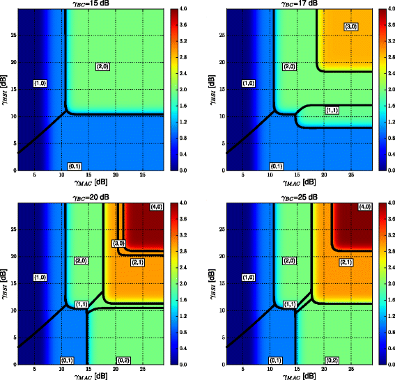
Throughput performance T LB and SNR mapping regions (including the optimal const. parameters (\(N_{b}^{\mathrm {I}},\,N_{s}^{\mathrm {I}}\))) for γ BC∈{15 dB, 17 dB,20 dB,25 dB}
-
The constellations with (N b >0, N s =0) provide the best performance in a substantial part of the medium-to-high γ HSI regions, depending on the actual γ MAC, γ BC.
-
The “combined” constellations (N b >0, N s >0) provide the maximal throughput (for sufficiently high γ BC) in relatively large regions of γ MAC, γ HSI (see the dominant throughput regions of \(\left (N_{b}^{\mathrm {I}},\,N_{s}^{\mathrm {I}}\right)=(2,1)\) for γ BC={20 dB, 25 dB}). Note that these constellations have a great potential for application in systems with limited or partial HSI (see [15]).
-
The BC channel SNR (γ BC) can significantly limit the performance of the system, even in the case where both γ MAC, γ HSI are relatively high (compare the results for γ BC=15 dB and γ BC=20 dB for γ MAC=γ HSI ≳15 dB). This behavior originates in the fact that \(\rho _{\text {BC}}^{2}\) decreases with growing N b +2N s and hence low γ BC essentially limits the maximum efficiently applicable cardinality of the relay output (\(\phantom {\dot {i}\!}2^{N_{b}+2N_{s}}\)-QAM) constellation. Equivalently, the optimal source constellation parameters \(\left (N_{b}^{\mathrm {I}},\,N_{s}^{\mathrm {I}}\right)\) can become limited by the bottleneck induced by weak relay →destination (BC) channels.
-
The constellations with odd N b are rarely dominant over the other strategies with identical N b +N s . This is a direct consequence of their relatively poor \(\rho _{\text {MAC}}^{2}\) Euclidean distance properties.

To support a viability of the adaptive constellation mapping scheme, we again evaluate the system performance in the HW real-world setup. Since the HW evaluation is heavily time-consuming, we analyze the throughput T USRP only for γ BC=20 dB and 0 dB≤γ MAC,γ HSI≤30 dB with a step-size 3 dB. The measured T USRP performance is available in Fig. 11. Close agreement between the T USRP and T LB can be observed again in the whole range of analyzed γ MAC, γ HSI (see Fig. 11).

Comparison of T LB and the throughput performance evaluated in a real-world adaptive HW setup (T USRP) for γ BC=20 dB. The SNR mapping regions (including the optimal const. parameters (\(N_{b}^{\mathrm {I}},\,N_{s}^{\mathrm {I}}\))) used in the HW evaluation are also emphasized in the figure
6 Channel coding
We have shown that Algorithm 1 is a strong tool for the design of source constellations suitable for arbitrary channel SNRs in the WBN system. However, even though the proposed constellations provide promising performance in the uncoded scenario, the extension to a coded system is desirable for practical wireless applications.
Considering the communication in uncoded WBNs (Fig. 2), there are many ways to improve its reliability through channel coding. In this paper, we propose one particular solution, based on the assumption that each source node splits its data into the basic and superposed part and then encodes these parts separately by two constituent channel encoders8. We believe that this approach provides the best insight into the channel-coding extension of WBN systems and hence we focus on its development in the rest of this section.
6.1 Per-link channel coding scheme for symmetric WBN with superposition modulations
In general, it is desirable to protect all individual transmissions in the system with error correction coding9. Accordingly, the relay node has to decode the desired data (including the particular WNC function) from its observation and then it should perform an additional re-encoding in order to protect the subsequent relay → destinations transmission. The resulting channel coding scheme (see Fig. 12) is introduced in the following text.

Relaying scheme in the encoded WBN system. SODEM stands for a soft-output demodulator, IC is the interference canceler. The channel encoders/decoders which are appended to the uncoded system are emphasized
6.1.1 Source processing
Source S A (likewise for S B ) wants to transmit a binary data word D A of length |D A |=|D B |=k D to its respective destination D A . Each data word D A is split into the basic and superposed part (similarly as in the uncoded case), i.e.,:
where \(d_{A,n}^{b},\,d_{A,n}^{s}\in \left \{ 0,1\right \} \) and \(k_{\mathbf {D}}^{b},\,k_{\mathbf {D}}^{s}\) are the lengths of the basic and superposed data sub-words \(\mathbf {D}_{A}^{b},\,\mathbf {D}_{A}^{s}\) (respectively).
Subsequently, individual \(\mathbf {D}_{A}^{b},\mathbf {\,D}_{A}^{s}\) are encoded by two separate linear binary encoders  (assumed identical at both sources), producing the constituent codewords as:


where  is the number of codeword symbols (equivalently the number of channel uses required to transmit the codeword) and
are codeword symbols of length N
b
(respectively N
s
) bits. The dimensionality of binary codewords is thus 
The constituent codewords \(\mathbf {C}_{A}^{b},\,\mathbf {C}_{A}^{s}\) are then forwarded to the joint constellation mapper  (provided by Algorithm 1), which produces a sequence of (N
s
+N
b
)-bit constellation symbols
(provided by Algorithm 1), which produces a sequence of (N
s
+N
b
)-bit constellation symbols  Note that in the encoded system it is the codeword symbols that are mapped to the desired constellation (instead of data symbols), but since \(\left |\mathbf {c}_{A}^{b}\right |=\left |\mathbf {c}_{B}^{b}\right |=N_{b}\) and \(\left |\mathbf {c}_{A}^{s}\right |=\left |\mathbf {c}_{B}^{s}\right |=N_{s}\), it is sufficient to formally substitute the codeword symbol \(\mathbf {c}_{i}=\left [\mathbf {c}_{i}^{b};\mathbf {c}_{i}^{s}\right ]\) for the data symbol \(\mathbf {d}_{i}=\left [\mathbf {d}_{i}^{b};\mathbf {d}_{i}^{s}\right ]\) in Algorithm 1 (lines 10, 15). The resulting constellation symbols are successively transmitted by S
A
(simultaneously with s
B,j
from S
B
) towards the relay node.
Note that in the encoded system it is the codeword symbols that are mapped to the desired constellation (instead of data symbols), but since \(\left |\mathbf {c}_{A}^{b}\right |=\left |\mathbf {c}_{B}^{b}\right |=N_{b}\) and \(\left |\mathbf {c}_{A}^{s}\right |=\left |\mathbf {c}_{B}^{s}\right |=N_{s}\), it is sufficient to formally substitute the codeword symbol \(\mathbf {c}_{i}=\left [\mathbf {c}_{i}^{b};\mathbf {c}_{i}^{s}\right ]\) for the data symbol \(\mathbf {d}_{i}=\left [\mathbf {d}_{i}^{b};\mathbf {d}_{i}^{s}\right ]\) in Algorithm 1 (lines 10, 15). The resulting constellation symbols are successively transmitted by S
A
(simultaneously with s
B,j
from S
B
) towards the relay node.
6.1.2 Relay processing
The crucial part of the encoded WBN system processing is based at the relay node. Like the uncoded case, the relay must decode jointly the superposed data sub-words \(\left (\mathbf {D}_{A}^{s},\,\mathbf {D}_{B}^{s}\right)\) along with the WNC functionof basic data sub-words \(\left (f\left (\mathbf {D}_{A}^{b},\mathbf {D}_{B}^{b}\right)=\mathbf {D}_{A}^{b}\oplus \mathbf {D}_{B}^{b}\right)\). While both \(\mathbf {d}_{A}^{s},\,\mathbf {d}_{B}^{s}\) can be decoded straightforwardly by the relay (using conventional single user decoders  ), the fundamental question is how to decode the WNC function \(f\left (\mathbf {d}_{A}^{b},\mathbf {d}_{B}^{b}\right)\) since both \(\mathbf {D}_{A}^{b},\,\mathbf {D}_{B}^{b}\) are encoded separately at sources S
A
, S
B
10. Fortunately, as proven in [13], the WNC function \(f\left (\mathbf {d}_{A}^{b},\mathbf {d}_{B}^{b}\right)\) can be decoded directly from the relay observation (5), if the particular source data words are encoded by the same linear encoder
), the fundamental question is how to decode the WNC function \(f\left (\mathbf {d}_{A}^{b},\mathbf {d}_{B}^{b}\right)\) since both \(\mathbf {D}_{A}^{b},\,\mathbf {D}_{B}^{b}\) are encoded separately at sources S
A
, S
B
10. Fortunately, as proven in [13], the WNC function \(f\left (\mathbf {d}_{A}^{b},\mathbf {d}_{B}^{b}\right)\) can be decoded directly from the relay observation (5), if the particular source data words are encoded by the same linear encoder  since
since

where \(\mathbf {C}_{A}^{b}\oplus \mathbf {C}_{B}^{b}\) itself is again a valid codeword and hence the WNC function \(f\left (\mathbf {d}_{A}^{b},\mathbf {d}_{B}^{b}\right)\) can be decoded directly from the relay observation (using a conventional single user decoder \(\mathcal {C}_{b}^{-1}\)).
After decoding all required data streams \(\left (\hat {\mathbf {D}}_{A}^{s},\,\hat {\mathbf {D}}_{B}^{s}, \hat {f}\left (\mathbf {D}_{A}^{b},\mathbf {D}_{B}^{b}\right)\right)\), the relay creates a joint data word \(\mathbf {D}_{R}=\left [\hat {\mathbf {D}}_{A}^{s},\hat {\mathbf {D}}_{B}^{s},\hat {f}\left (\mathbf {D}_{A}^{b},\mathbf {D}_{B}^{b}\right)\right ]\) and re-encodes it as  . The encoded data are then mapped to the output \(\phantom {\dot {i}\!}2^{N_{R}}\)-QAM (where N
R
=2N
s
+N
b
) constellation symbols
. The encoded data are then mapped to the output \(\phantom {\dot {i}\!}2^{N_{R}}\)-QAM (where N
R
=2N
s
+N
b
) constellation symbols  and broadcast by the relay to both destination nodes.
6.1.3 Destination processing
As in the uncoded case, destinations D A , D B firstly store the signal received in the MA phase, and then, after decoding the relay data word D R (from the signal received in the BC phase), both destinations can perform IC to remove the unintended superposed codewords from the MA phase signal to get the desired HSI and then finally recover the desired data (see Fig. 12 for the details).
6.2 Analysis of transmission rates
The last step in the design of a feasible modulation and coding scheme for WBN (see Fig. 12) is to identify the range of permissible transmission rates for the basic (r b ), superposed (r s ) and relay output (r R ) data streams. To achieve this goal, we analyze the constellation constrained (CC) capacities [31] of the proposed source constellations, including the CC capacity of the conventional relay output \(\phantom {\dot {i}\!}2^{N_{R}}\)-QAM alphabets (used in the BC phase of communication).
The transmission rates are defined in bits per channel use, and hence \(r_{i}=N_{i}\cdot \nicefrac {k_{\mathbf {D}}^{i}}{n_{\mathbf {C}}^{i}}\), where N
i
is the number of bits per channel symbol/use in the data stream i,i∈{b,s,R}. In accordance with the definition of source and relay codewords, we assume that each communication round requires  channel uses, where the length of both MA and BC phase is set to
  channel uses. Note that the assumption that BC and MA phases have identical length is generally only suboptimal (see e.g., [1, 15]), but nevertheless, it is a common assumption in practical systems and hence, we limit our attention to this particular case.
6.2.1 Relay observation
After splitting the source data streams, the whole system can be interpreted as a 4-user system where the relay has to decode the data \(\mathbf {D}_{A}^{s},\,\mathbf {D}_{B}^{s},\,f\left (\mathbf {D}_{A}^{b},\mathbf {D}_{B}^{b}\right)\) from the virtual 3-user \(\left (S_{A}^{s},\,S_{B}^{s},\,S_{AB}^{b}\right)\) multiple-access channel observation (see Fig. 12). Unfortunately, since one of the users (\(S_{AB}^{b}\)) is only virtual, we cannot simply claim that the region of achievable rates in this virtual channel can be derived directly from the conventional cut-set bound analysis (see e.g., [18, 32]), but rather a careful information-theoretic analysis would be required to identify the exact rate region. However, such analysis is far beyond the scope of this paper, and hence, for simplicity reasons, we only conjecture that the eligible source rates (r b , r s ) are limited by the conventional CC multiple-access capacity region [18, 32], which can be defined by the following set of mutual informations I(▪;▪):
where (13), (14)–(16), and (17)–(19) are the corresponding third, second, and first order cut-set bounds (respectively). As we show later, the CC MAC region (as defined by (13)–(21)) provides a reasonable estimate of the maximal achievable source transmission rate pair (r b , r s ) in WBN.
Since the superposed data sub-words \(\mathbf {d}_{A}^{s},\,\mathbf {d}_{B}^{s}\) are mapped to orthogonal ASK sets (Algorithm 1), the 2nd order cut-set bound \(I\left (x;\mathbf {c}_{A}^{s},\mathbf {c}_{B}^{s}|f\left (\mathbf {c}_{A}^{b},\mathbf {c}_{B}^{b}\right)\right)\) (14) is equivalent to \(I\left (x;\mathbf {c}_{A}^{s}|\mathbf {c}_{B}^{s},f\left (\mathbf {c}_{A}^{b},\mathbf {c}_{B}^{b}\right)\right)+I\left (x;\mathbf {c}_{B}^{s}|\mathbf {c}_{A}^{s},f\left (\mathbf {c}_{A}^{b},\mathbf {c}_{B}^{b}\right)\right)\) (defined in Eqs. (17) and (18)), which can be proven easily by the chain rule for mutual information of orthogonal signal sets (see [18]). Moreover, due to the assumed WBN system symmetry, the cut-set bounds defined in Eqs. (17) and (18) are identical, and the same is true for the pair of cut-set bounds defined in (15) and (16). Consequently, the CC multiple-access capacity region is completely defined by the four inequalities in (13), (15), (17), and (19).
6.2.2 Effective HSI channels
In addition to the successful relay decoding, the transmission rate of the basic information stream r b must guarantee that the HSI (given by the unintended data sub-words \(\mathbf {D}_{A}^{b}\) at D B and \(\mathbf {D}_{B}^{b}\) at D A ) can be decoded at both destinations (after perfect IC of superposed data codewords \(\mathbf {C}_{A}^{s}\) at D B and \(\mathbf {C}_{B}^{s}\) at D A from the stored MA phase signal). Note that since we assume that the relay has already successfully decoded \(f\left (\mathbf {d}_{A}^{b},\mathbf {d}_{B}^{b}\right)\) at this step, it can be efficiently exploited in the decoding process, resulting in the following upper-bounds on the source rate r b :
where \(z_{A}^{\text {IC}},\,z_{B}^{\text {IC}}\) are the efficient HSI observations (after perfect IC) at D A , D B (respectively)—see Fig. 12. Both (20) and (21) are identical in the symmetric WBN system.
6.2.3 Relay broadcast channel
The relay rate r
R
must guarantee that its data word \(\mathbf {D}_{R}=\left [\hat {\mathbf {D}}_{A}^{s},\hat {\mathbf {D}}_{B}^{s},\hat {f}\left (\mathbf {D}_{A}^{b},\mathbf {D}_{B}^{b}\right)\right ]\) with length  can be sent to both destinations in channel uses. In addition to this, to enable successful decoding of the relay data at both destinations, the relay transmission rate r
R
must be below the CC capacities of the corresponding relay →destination channels. Thus, the relay rate should be set to r
R
=r
b
+2r
s
, which gives us the last two inequalities for r
b
, r
s
:
can be sent to both destinations in channel uses. In addition to this, to enable successful decoding of the relay data at both destinations, the relay transmission rate r
R
must be below the CC capacities of the corresponding relay →destination channels. Thus, the relay rate should be set to r
R
=r
b
+2r
s
, which gives us the last two inequalities for r
b
, r
s
:
where both cut-set bounds (22), (23) are identical due to the system symmetry.
6.3 Transmission rate region for fixed source constellation
To identify the region  of eligible transmission rates for a fixed (N
b
,N
s
) source constellation, we can evaluate numerically11 the set of relevant cut-set bounds (i.e., (13), (15), (17), (19), (20), and (22)) for given SNR conditions in the symmetric WBN system (γ
MAC, γ
BC, γ
HSI). An example analysis of the source transmission rate region
of eligible transmission rates for a fixed (N
b
,N
s
) source constellation, we can evaluate numerically11 the set of relevant cut-set bounds (i.e., (13), (15), (17), (19), (20), and (22)) for given SNR conditions in the symmetric WBN system (γ
MAC, γ
BC, γ
HSI). An example analysis of the source transmission rate region  for the (N
b
=2, N
s
=1) source constellation is visualized in Fig. 13 for two different SNR setups. The cut-set bound rate region
for the (N
b
=2, N
s
=1) source constellation is visualized in Fig. 13 for two different SNR setups. The cut-set bound rate region  is emphasized by the shaded area and the rate pair with maximal r
b
+r
s
is identified in the figure. We have assumed that the source → relay channels are AWGN (or equivalently that perfect source phase prerotation [23–25] is implemented) in the numerical evaluation.
is emphasized by the shaded area and the rate pair with maximal r
b
+r
s
is identified in the figure. We have assumed that the source → relay channels are AWGN (or equivalently that perfect source phase prerotation [23–25] is implemented) in the numerical evaluation.

Numerically evaluated cut-set bounds (mutual information for finite input constellations) for (N b =2,N s =1) source constellations and 16-QAM at the relay. The particular SNR conditions are available in the titles of both sub-figures
7 Performance analysis II: adaptive encoded system
As shown in Fig. 13, the performance of the encoded WBN system is, like in the uncoded case, influenced by the immediate SNR conditions (given by γ
MAC, γ
BC, γ
HSI) and hence an adaptive modulation and coding schemeis again of interest. However, before we introduce theSNR mapping operation for the encoded system, we show that the cut-set bound rate regions  (as introduced in the preceding section) provide a reasonable approximation of achievable source transmission rate pairs in the symmetric WBN system. In the whole section, we assume (for simplicity reasons) that perfect source phase prerotation [23–25] is implemented in the system, virtually reverting the source → relay channels to the AWGN case.
7.1 Numerical simulation of encoded WBN system throughput
We implement all constituent channel encoders in the WBN system (see Fig. 12) as parallel concatenated turbo codes with random interleavers of length  symbols. By proper puncturing [33] of the channel encoders’ outputs, we are able to set the source transmission rates (separately for the basic and superposed streams) to an almost arbitrary value in the range (1/3→1). We set the initial source transmission rates to the maximum
  (as evaluated in Fig. 13) and by proper adjustment of the puncturing operation we successively decrease the source transmission rates r
b
, r
s
until the SER performance drops to zero. As one can see in Fig. 13, the achieved transmission rate pairs are relatively close to the maximal permissible values and hence we can consider the cut-set bound rate region
(as evaluated in Fig. 13) and by proper adjustment of the puncturing operation we successively decrease the source transmission rates r
b
, r
s
until the SER performance drops to zero. As one can see in Fig. 13, the achieved transmission rate pairs are relatively close to the maximal permissible values and hence we can consider the cut-set bound rate region  (as discussed in Section 6.3) to be a reasonable approximation of the achievable source transmission rate region.
7.2 Maximal throughput of the adaptive modulation-coding scheme
As in the uncoded case, the source nodes S A , S B in the adaptive modulation-coding WBN system must be aware of the particular mapping operation \(\left (\hat {\gamma }_{\text {MAC}},\,\hat {\gamma }_{\text {BC}},\,\hat {\gamma }_{\text {HSI}}\right)\mapsto \left (N_{b}^{\text {II}},\,N_{s}^{\text {II}};\,r_{b}^{\text {II}},\,r_{s}^{\text {II}}\right),\) providing the set of optimal (in the sense of maximal throughput) constellation/encoder parameters for the given SNR conditions \(\left (\hat {\gamma }_{\text {MAC}},\,\hat {\gamma }_{\text {BC}},\,\hat {\gamma }_{\text {HSI}}\right)\). Note that, in general, all adaptive system parameters are functions of the actual SNR conditions in the system. However, we mostly omit the explicit notation in the following text to aid readability.
The desired adaptive system parameters can be obtained in the following two-step procedure. First of all, we analyze the cut-set bound rate regions  (as discussed in Section 6.3) to identify the maximal encoded system throughput \(T_{C}^{(N_{b},N_{s})}\) for a fixed source constellation (N
b
,N
s
):
(as discussed in Section 6.3) to identify the maximal encoded system throughput \(T_{C}^{(N_{b},N_{s})}\) for a fixed source constellation (N
b
,N
s
):

Then, an exhaustive search over the constellation parameters N b , N s can be performed to find the maximum encoded system throughput \(T_{C}^{\text {max}}\) for the given SNR conditions (γ MAC, γ BC, γ HSI):
where \(\left (N_{b}^{\text {II}},\,N_{s}^{\text {II}}\right)\) are the optimal source constellation parameters. The corresponding optimal source transmission rates (25) are given simply by \(r_{b}^{\text {II}}=r_{b}^{\text {max}}\left (N_{b}^{\text {II}},\,N_{s}^{\text {II}}\right)\), \(r_{s}^{\text {II}}=r_{s}^{\text {max}}\left (N_{b}^{\text {II}},\,N_{s}^{\text {II}}\right)\).
The SNR mapping regions (including the throughput \(T_{C}^{\text {max}}\)) for the adaptive modulation and coding scheme in WBN are evaluated as a function of γ MAC, γ HSI in Fig. 14 for γ BC∈{7.5 dB, 15 dB}. As one can see in Fig. 15, the increased reliability of transmissions on all individual channels in WBN (as compared to the uncoded system) translates directly into a significant enhancement of throughput performance in the whole range of observed SNRs. This observation justifies the viability of the proposed channel coding scheme.

Maximal encoded system throughput \(T_{C}^{\text {max}}\) for γ BC=7.5 dB and γ BC=15 dB

Throughput enhancement \(\Delta T_{C}=T_{C}^{\text {max}}-T_{\text {LB}}\) [bits/channel use] of the coded over uncoded WBN system for γ BC=7.5 dB and γ BC=15 dB. Note that 0.75≤Δ T C ≤2 in the analyzed range of channel SNRs
7.3 Robustness analysis
In this section, we show that the proposed modulation and coding scheme is viable even if the real-world conditions induce some deviations from the system model assumed in this paper. From a practical point of view, we would be interested mainly in the situation, where a direct channel between a source and its desired destination is present (see Fig. 16). Even though this “direct” channel can be relatively weak, it inevitably affects the destinations’ HSI observations. In addition to this, we analyze the system where source phase pre-rotation is switched off (or ineffective due to rapid channel dynamics), and thus the relay faces a multiple-access channel with a varying source channel phase offset. This assumption is valid for a practical system where the applicability of source phase pre-rotation is limited due to the unavailable ideal feedback channel or because of the undesirable delay induced by the feedback in the pre-rotation operation. To demonstrate the robustness of the proposed modulation and coding strategy, we compare the WBN performance results achieved by the Monte-Carlo numerical evaluation (see section 7.1) with USRP HW measurements. While in the numerical evaluation we still keep the idealized assumptions as defined by our system model (i.e. no direct source →destination channels, perfect channel phase pre-rotation), in the HW measurements we now allow all data communication to be performed through real wireless channels (compare with the HW setup in Section 4.2), introducing inevitably some direct channel observation at both destinations. In addition, we allow the source phase pre-rotation to be switched off in the HW measurements. The channel SNRs γ MAC,γ HSI in the HW measurements can be controlled by the source transmit power adjustment and similarly, particular values of γ BC can be set up by the adjustment of the relay transmit power.

Direct channel at destination D B in the robustness analysis (likewise, a direct channel is assumed to be present also at D A )
To perform a comparison of the idealized numerical evaluation with the HW robustness measurements, we evaluate the range of SNRs where a zero error rate performance can be achieved for fixed constellations and channel encoder rates (N b ,N s ,r b ,r s ). To achieve this, we identify the triplet of SNRs (γ MAC,γ HSI, γ BC) providing a zero-error rate performance at both destinations. This SNR triplet then defines the lower-most corner of the SNR region where a zero error rate performance can be achieved (see Fig. 17). We can conclude that:
-
The presence of direct links requires only slightly increased values of (γ MAC,γ HSI, γ BC) to ensure a zero error-rate performance for the fixed (N B ,N S ,r b ,r s ). However, it is evident that a modification of the proposed modulation and coding scheme could be desirable to fully harness the information transmitted over direct source destination channels.
Fig. 17 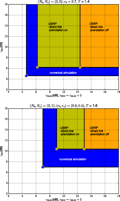
Robustness analysis for two fixed (N b ,N s ,r b ,r s ) scenarios
-
The source channel phase asynchrony in the system with direct links further degrades the performance on the sources → relay channel and thus an additional increase of the source transmission power (and consequently γ MAC) is required to provide a zero-error rate. However, γ BC is not affected in this case, as the channel pre-rotation does not have any impact on the relay → destination performance.

7.4 Benchmarking with the state of the art three-step scenarios
For a more advanced comparison of the proposed method, we consider two conventional three-step communication scenarios.
7.4.1 Reference three-step scenarios
In the first scenario, both sources transmit their information one by one, but the relay is allowed to combine the received (fully decoded) data packets into the network coded packet f(d A ,d B )=d A ⊕d B and HSI channels are necessary to retrieve the desired information at both sources. This is the traditional network coding approach (see Fig. 18).

Three-step reference scenario with conventional network coding
The second scenario is equivalent to conventional routing, where the sources subsequently transmit their data packet towards the relay. The relay then sends complete source information (no NC coding is applied) and thus the HSI channels are completely ignored (see Fig. 19).

Three-step reference scenario with conventional routing
7.4.2 Implementation details for reference scenarios
To provide a fair comparison, in both reference scenarios, we assume that the sources transmit with twice the power, as their transmit time is essentially halved when compared with the two-step scenarios. We assume QAM(N) constellation and adaptively look for N,r maximizing the throughput as in the proposed Section 7.2.
7.4.3 Maximum transmission rates for the three-step reference scenarios
The theoretical limits for the considered three-step scenarios can easily be derived (see [15]) as
where CA(γ)= log2(1+γ) denotes the conventional point-to-point channel capacity for Gaussian channels [18].
These bounds serve as an initial step for the tuple (rate, alphabet cardinality) optimization as in Section 6.2 but also as an ultimate theoretical bound of the individual reference strategies.
7.4.4 Numerical results
Within this experiment, we evaluated the following situations on our USRP platform:
-
The proposed adaptive constellation design from Section 7.2 based on the optimized tuple (r b ,r s ,N b ,N s ) for each measured point (HW-pre-rotation on).
-
The proposed adaptive constellation design with assumptions violated (pre-rotation off).
-
Both three-step reference scenarios introduced in Section 7.4.1.
-
Fundamental theoretical limits for the conventional reference three-step scenarios.
In all measured cases, we manually selected the tuple maximizing the throughput. Our starting point was the theoretical analysis, but this analysis does not take into account the imperfect channel code and available discrete channel code rates (0.4, 0.5, …, 0.9). We also considered N b ≤2, N s ≤1 for simplicity12.
We considered two setups:
-
Strong HSI and equal MA and BC. This scenario is suited for standard wireless network coding, because it can efficiently utilize the strong HSI channel. See Fig. 20 for the corresponding result. As one can see, the proposed framework significantly outperforms both reference three-step scenarios as well the corresponding theoretical limits even if the pre-rotation is off! The bottleneck for the three-step routing is the BC channel because it needs to pass twice the amount of data from relay to destinations compared to all other schemes. The three-step NC approach does not suffer from this and therefore its performance is a bit better, nevertheless we pay for orthogonality in the MA stage. The performance of the proposed framework is superior to both reference models.
Fig. 20 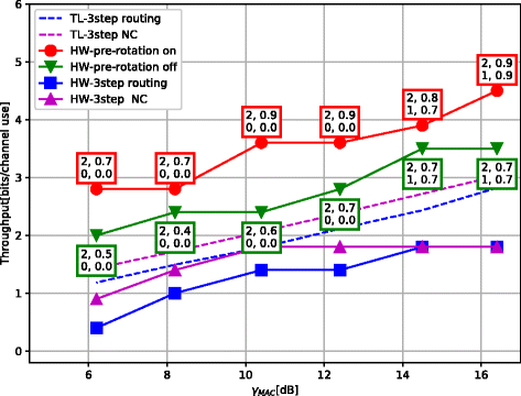
Performance comparison for the setup γ BC≈γ MAC and γ HSI≈γ MAC+3dB. The numbers in boxes correspond with particular values (first row: (N b ,r b ), second row: (N s ,r s )) achieving a given maximal throughput
-
Strong BC channel refers (among others) to a case with high relay power. The result is shown in Fig. 21. The three-step routing works much better when compared to the previous case, because of the strong BC channel. The conventional three-step network coding scheme suffers with a weak HSI channel. The proposed design again significantly outperforms both reference three-step scenarios. We should stress, that the performance gain is also achieved with partial usage of the weak HSI channel.
Fig. 21 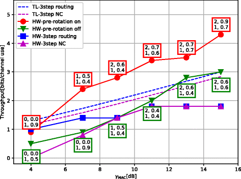
Performance comparison for the setup γ BC≈γ MAC+5dB and γ HSI≈γ MAC-1dB. The numbers in boxes correspond with particular values (first row: (N b ,r b ), second row: (N s ,r s )) achieving a given maximal throughput


The saturation of the reference three-step strategies for high SNRs is a consequence of weaker performance of the underlaying channel code, where the rate of the code is adjusted by means of puncturing technique.
8 Conclusions
In this paper, we have proposed a systematic algorithm for the design of two-source constellations in the WBN system. The Algorithm 1 allows the matching of the constellation parameters to virtually any SNR conditions in the system, enabling a direct implementation of the adaptive constellation mapping scheme. The viability of the proposed constellation design was verified by means of numerical analysis, simulations and through real-world HW experiments (based on Ettus Research USRPs), including a HW-based robustness analysis.
Even in the uncoded scenario, the proposed constellations are able to significantly boost the WBN system throughput, and hence even their uncoded implementation can be interesting, especially in some basic wireless networks where channel coding is avoided to reduce complexity (e.g., in sensor networks). Furthermore, we have shown that the proposed source constellation design can be readily extended with appropriately designed channel encoding/decoding operations, significantly improving the reliability (including the throughput) of the resulting adaptive modulation-coding scheme.
In future work, we would like to focus on a full adaptive HW implementation of the proposed system, where the impact of several other parameters (e.g., channel fading and dynamics, asymmetry of channel gains, etc.) can significantly affect the system performance and possibly even require some modifications of the adaptive system design.
9 Nomenclature
-
WBN Wireless Butterfly Network
-
WNC Wireless Network Coding
-
HW Hardware
-
SNR Signal to Noise Ratio
-
SC Superposition Coding
-
HSI Hierarchical Side Information
-
DEM Demodulator
-
IC Interference Cancellation
-
MA Multiple Access
-
AWGN Additive White Gaussian Channel
-
ASK Amplitude Shift Keying
-
QAM Quadrature Amplitude Modulation
-
SER Symbol Error Rate
-
FER Frame Error Rate
-
SDR Software Defined Radio
-
USRP Universal Software Radio Peripherals
-
UHD USRP Hardware Driver
-
CP Cyclic Prefix
-
ODFD Orthogonal Frequency Division Multiplexing
-
DC Direct Current
-
MIMO Multiple Input Multiple Output
-
QPSK Quadrature Phase Shift Keying
-
UDP User Datagram Protocol
-
BC Broadcast Channel
-
MAC Multiple Access Channel
-
SODEM Soft Output Demodulator
-
CC Constellation Constrained
10 Endnotes
1 Modification of the system model for the coded case will be provided in Section 6, together with a discussion on the design of individual channel encoders for particular information streams in the system.
2 Modulo-sum [11, 34, 35] and bit-wise exclusive-or (XOR) [3, 23] hierarchical functions are commonly discussed in the WNC literature, however, unlike the bit-wise XOR, implementation of channel coding for the Modulo-sum mapping is a standalone research problem and hence it is out of the scope of this paper.
3 Note that this also includes the system with perfect source phase prerotation [23–25], which can be obtained by a generalization of the scaling coefficients as \(L^{\prime }_{n}=L_{n}e^{-\operatorname {j}\measuredangle h_{SR}}\), where h SR is the corresponding source →relay channel.
4 The evaluated \(P_{e,\text {UB}}^{SER}\) is an upper-bound of \(P_{e}^{\text {SER}}\), since an error in MA/BC phase does not necessarily induce an error in the overall communication chain of the uncoded system. This is especially true if the error occurs in the superposed bits \(\mathbf {d}_{B}^{s}\) used for interference cancellation processing at D A .
5 In AWGN channel, the resulting superimposed constellation has too many overlaps for the reference source QPSK constellations, preventing a successful multi-user decoding of both of the separate user data streams in the uncoded system.
6 It can be shown that for constant N b +N s the minimum Euclidean distance \(\rho _{\text {HSI}}^{2}\) grows with decreasing N b , resulting in a more efficient utilization of “imperfect” HSI channels [15, 36] and consequently in a more reliable overheard HSI for the constellations with lower (non-zero) N b .
7 The estimated SNR parameters (\(\hat {\gamma }_{\text {MAC}},\,\hat {\gamma }_{\text {BC}},\,\hat {\gamma }_{\text {HSI}}\)) must be delivered to both sources by a feedback channel from the relay and/or destinations. The particular implementation of this feedback transmission is beyond the scope of this paper and hence (for the sake of simplicity) we assume that these parameters are made available at both sources by a genie. Note that in the HW evaluation, the required feedback is provided via UDP connection.
8 In a more general approach, each source data word is split into N b +N s parallel data sub-words that are encoded separately using the principles of multilevel coding (see e.g. [37]). However, the development of a general multilevel coding scheme for WBN is beyond the scope of this paper.
9 Alternatively, a primitive end-to-end coding scheme can be designed, performing the channel coding solely at sources S A , S B and channel decoding (potentially computationally intensive) solely at destinations D A , D B , while leaving the relay R to operate on a symbol-by-symbol basis (as in the uncoded system). Unfortunately, this approach is only sub-optimal, as in this case the particular transmissions on source →relay and relay →destination channels are not individually protected by channel coding.
10 Note that separate decoding of \(\mathbf {D}_{A}^{b},\,\mathbf {D}_{B}^{b}\) and subsequent evaluation of \(f\left (\mathbf {d}_{A}^{b},\mathbf {d}_{B}^{b}\right)\) (i.e. conventional joint/multi-user decoding concatenated with traditional network coding [38]) can significantly limit the performance of the system [13].
11 The (conditional) probability density function \(p\left (x|\mathbf {c}_{A}^{s},\mathbf {c}_{B}^{s},f\left (\mathbf {c}_{A}^{b},\mathbf {c}_{B}^{b}\right)\right)\) which is required for the evaluation of particular mutual information in (13)-(21) can be obtained by a proper marginalization operation \(p\left (x|\mathbf {c}_{A}^{s},\mathbf {c}_{B}^{s},f\left (\mathbf {c}_{A}^{b},\mathbf {c}_{B}^{b}\right)\right)=\text {Pr}\left \{ f\left (\mathbf {c}_{A}^{b},\mathbf {c}_{B}^{b}\right)\right \}\cdot \sum _{\mathbf {c}_{A}^{b},\mathbf {c}_{B}^{b}:f \left (\mathbf {c}_{A}^{b},\mathbf {c}_{B}^{b}\right)} p\left (x|\mathbf {c}_{A}^{s},\mathbf {c}_{B}^{s},\mathbf {c}_{A}^{b},\mathbf {c}_{B}^{b}\right)\), where \(p\left (x|\mathbf {c}_{A}^{s},\mathbf {c}_{B}^{s},\mathbf {c}_{A}^{b},\mathbf {c}_{B}^{b}\right)\) is the likelihood function. For more details on the evaluation of CC capacity for finite input constellations see e.g. [13, 32].
12 The higher order strategies like (N b =4,N s =0) performed similarly as considered (N b =2,N s =1) in our simulations. Note that much stronger solution based on the modulo-sum channel coding and wireless network coding function is available [35], nevertheless implementation of the non-binary channel code suitable for the USRP is challenging.
References
P Popovski, H Yomo, in Proc. IEEE Internat. Conf. on Commun. (ICC). Physical network coding in two-way wireless relay channels (IEEE Conference PublicationsPiscataway, 2007).
B Nazer, M Gastpar, Reliable physical layer network coding. Proc. IEEE. 99(3), 438–60 (2011).
S Zhang, S-C Liew, L Lu, Physical-layer network coding: Tutorial, survey, and beyond. Phys. Commun. 2012:, 1–39 (2012). doi:10.1016/j.phycom.2012.05.002.
T Koike-Akino, P Popovski, V Tarokh, in Proc. IEEE Global Telecommunications Conf. (GlobeCom). Denoising maps and constellations for wireless network coding in two-way relaying systems (IEEE Conference PublicationsPiscataway, 2008).
J Liu, M Tao, Y Xu, in Proc. IEEE Internat. Conf. on Commun. (ICC). Pseudo exclusive-OR for LDPC coded two-way relay block fading channels (IEEE Conference PublicationsPiscataway, 2011), pp. 1–5.
K Yasami, A Razi, A Abedi, Analysis of channel estimation error in physical layer network coding. IEEE Commun. Lett. 15(10), 1029–31 (2011). doi:10.1109/LCOMM.2011.082011.110301.
T Uricar, J Sykora, Non-uniform 2-slot constellations for bidirectional relaying in fading channels. IEEE Commun. Lett. 15(8), 795–7 (2011).
S Zhang, S-C Liew, PP Lam, in Proc. IEEE Inf. Theory Workshop (ITW). On the synchronization of physical-layer network coding (IEEE Conference PublicationsPiscataway, 2006), pp. 404–408.
F Rossetto, M Zorzi, in Proc. IEEE Workshop on Signal Processing Advances in Wireless Communications. On the design of practical asynchronous physical layer network coding (IEEE Conference PublicationsPiscataway, 2009), pp. 469–473.
Y Huang, S Wang, Q Song, L Guo, A Jamalipour, Synchronous physical-layer network coding: a feasibility study. IEEE Trans. Wireless Commun. 12(8), 4048–4057 (2013).
P Prochazka, T Uricar, D Halls, J Sykora, in Proc. IEEE Int. Conf. on Commun. (ICC). Relaying in butterfly networks: superposition constellation design for wireless network coding (IEEE Conference PublicationsLondon, 2015), pp. 1–7.
B Nazer, M Gastpar, in Proc. IEEE Internat. Symp. on Inf. Theory (ISIT). Compute-and-forward: Harnessing interference with structured codes (IEEE Conference PublicationsPiscataway, 2008), pp. 772–776.
J Sykora, A Burr, Layered design of hierarchical exclusive codebook and its capacity regions for HDF strategy in parametric wireless 2-WRC. IEEE Trans. Veh. Technol. 60(7), 3241–52 (2011).
T Uricar, B Qian, J Sykora, WH Mow, in Proc. IEEE Wireless Commun. Network. Conf. (WCNC). Superposition coding for wireless butterfly network with partial network side-information (IEEE Conference PublicationsShanghai, 2013), pp. 1–6.
T Uricar, B Qian, J Sykora, WH Mow, Wireless (physical layer) network coding with limited hierarchical side-information: Maximal sum-rates in 5-node butterfly network. IEEE Trans. Wireless Commun. 13(10), 5582–95 (2014).
IW-H Ho, SC Liew, L Lu, in Proc. IEEE Internat. Symp. on Inf. Theory (ISIT). Feasibility study of physical-layer network coding in 802.11p VANETs, (2014), pp. 646–650. doi:10.1109/ISIT.2014.6874912.
P Prochazka, WNC tutorial—constellation design for butterfly network. http://pavel.prochazka.info/tutorial/const_design_WNC. Accessed 28 Dec 2016.
TM Cover, JA Thomas, Elements of information theory (John Wiley & Sons, The Atrium, Southern Gate, Chichester PO19 8SQ, UK, 1991).
TS Han, K Kobayashi, A new achievable rate region for the interference channel. IEEE Trans. Inf. Theory. 27:, 49–60 (1981).
N Shende, BS Rajan, in Proc. National Conference on Communications (NCC). On the achievable rate of AWGN relay channel with finite input constellations (IEEE Conference PublicationsPiscataway, 2012), pp. 1–5.
P Popovski, E de Carvalho, Improving the rates in wireless relay systems through superposition coding. IEEE Trans. Wireless Commun. 7(12), 4831–6 (2008).
PA Hoeher, T Wo, Superposition modulation: myth and facts. IEEE Communications Mag. 49(12), 110–6 (2011).
T Koike-Akino, P Popovski, V Tarokh, Optimized constellations for two-way wireless relaying with physical network coding. IEEE J. Sel. Areas Commun. 27(5), 773–87 (2009).
S Zhang, S-C Liew, Applying physical-layer network coding in wireless networks. EURASIP J. on Wireless Comm. and Netw. 2010:, 1–12 (2010). doi:10.1155/2010/870268.
A Li, Y Yan, H Kayama, An enhanced denoise-and-forward relaying scheme for fading channel with low computational complexity. IEEE Signal Process. Lett. 15:, 857–860 (2008).
E Research, N200/N210 Product overview. https://www.ettus.com/content/files/07495_Ettus_N200-210_DS_Flyer_HR_1.pdf. Accessed 12 Feb 2016.
GNURadio, GNURadio overview. http://gnuradio.org/redmine/projects/gnuradio. Accessed 12 Feb 2016.
T Hynek, D Halls, J Sykora, in Proc. European Wireless Conf. (EW). Practical implementation of cloud initialization procedure for wireless physical layer network coding clouds (VDE Conference PublicationsBerlin, 2014), pp. 1–6.
D Halls, W Thompson, S Galimberti, S Savazzi, T Hynek, J Sykora, J Coon, Evaluation of practical system constraints, DIWINE deliverable D5.12 (2014). Technical report, FP7 ICT Objective 1.1 - The Network of the Future.
E Research, OctoClock-G Product overview. https://www.ettus.com/product/details/OctoClock-G. Accessed 12 Feb 2016.
E Biglieri, Coding for wireless channels (Springer, 233 Spring Street, New York, NY 10013-1578,USA, 2010).
J Harshan, BS Rajan, On two-user gaussian multiple access channels with finite input constellations. IEEE Trans. Inf. Theory. 57(3), 1299–327 (2011).
CB Schlegel, LC Perez, Trellis and turbo coding: iterative and graph-based error control coding (John Wiley & Sons, The Atrium, Southern Gate, Chichester PO19 8SQ, UK, 2015).
M Hekrdla, J Sykora, in Vehicular Technology Conference (VTC Spring), 2013 IEEE 77th. On indexing of lattice-constellations for wireless network coding with modulo-sum decoding (IEEE Conference PublicationsPiscataway, 2013), pp. 1–6.
P Prochazka, Nonbinary channel coded physical layer network coding over modulo-sum algebraic ring structures. IEEE Commun. Lett. 20(3), 538–41 (2016).
T Uricar, J Sykora, Non-uniform 2-slot constellations for relaying in butterfly network with imperfect side information. IEEE Commun. Lett. 16(9), 1369–72 (2012).
U Wachsmann, RFH Fischer, JB Huber, Multilevel codes: theoretical concepts and practical design rules. IEEE Trans. Inf. Theory. 45(5), 1361–91 (1999).
RW Yeung, S-YR Li, N Cai, Z Zhang, Network Coding Theory (NOW Publishers, 2600 AD Delft, The Netherlands, 2006).
Funding
This work has been performed in the framework of the European research project DIWINE, which is partly funded by the European Union under its FP7 ICT Objective 1.1 - The Network of the Future. Work of Pavel Prochazka and Tomas Uricar was also partially supported by the Grant Agency of the Czech Technical University in Prague, SGS project SGS16/094/OHK3/1T/13.
Availability of data and materials
We are aware that the presented topic is difficult to understand without very specific background in wireless network coding. To help the reader to overcame this problem, we created a short tutorial [17]. The tutorial first motivates the constellation design, then it shortly introduces the wireless network coding principle, its relation to conventional network coding. Many visual demonstrations of the proposed constellation design can be also found there. In addition to this, the supplementary Python code is available to the reader so that one can touch the topic also by means of implemented algorithms.
Declarations
This work was partly reported in IEEE ICC [11].
Author information
Authors and Affiliations
Corresponding author
Ethics declarations
Competing interests
The authors declare that they have no competing interests.
Publisher’s Note
Springer Nature remains neutral with regard to jurisdictional claims in published maps and institutional affiliations.
Rights and permissions
Open Access This article is distributed under the terms of the Creative Commons Attribution 4.0 International License(http://creativecommons.org/licenses/by/4.0/), which permits unrestricted use, distribution, and reproduction in any medium, provided you give appropriate credit to the original author(s) and the source, provide a link to the Creative Commons license, and indicate if changes were made.
About this article

Cite this article
Prochazka, P., Uricar, T., Halls, D. et al. Design of adaptive constellations and error protection coding for wireless network coding in 5-node butterfly networks. J Wireless Com Network 2017, 154 (2017). https://doi.org/10.1186/s13638-017-0935-y
Received:
Accepted:
Published:
DOI: https://doi.org/10.1186/s13638-017-0935-y