- Research
- Open access
- Published:
Load balancing mechanism for clustered PMIPv6 protocol
EURASIP Journal on Wireless Communications and Networking volume 2018, Article number: 135 (2018)
Abstract
Proxy Mobile IPv6 (PMIPv6) has become a credible member of pertinent research areas. This is attributed mainly to its capability of enabling mobility without imposing constraints or requirements on the mobile node (MN). This MN shield is enabled due to the transferring of mobility-related signaling to a new entity, which is called Mobile Access Gateway (MAG). However, associating MNs to a specific MAG inside the PMIPv6 network increases the MAG load probability. Thus, several research have enhanced the PMIPv6 protocol to improve its basic specifications and performance. Strategies include protocols, which apply the clustering technique to enhance the overall performance of the PMIPv6 in terms of routing, scalability, lifetime, and load balancing. The load balancing mechanism is considered in the non-clustered protocols. However, this mechanism has not been adopted in clustering-based protocols. Thus, pertaining to the load and the respective assignments is critical. In this article, to address these issues, a new load balancing mechanism is proposed among MAGs for Cluster-based Proxy Mobile IPv6 (CSPMIPv6) protocol. The signaling within the CSPMIPv6 has been enhanced to support the proposed load balancing mechanism. The proposed mechanism employs the inter- and intra-domain on a frequent basis to select the best MAG among the candidate MAGs. The new mechanism has improved the performance to create an evident improvement in terms of average queuing delay, handover latencies, transmission rate, end-to-end delay, and packet loss as compared to the LBM-PMIPv6 mechanism and CSPMIPv6 protocol.
1 Introduction
In Mobile Internet Protocol (MIP), the high involvement of MNs in the mobility-related signaling causes several serious issues. Among the issues are long handover latency and excessive signaling [1]. The MN is required to register with the home agent (HA) whenever the MN changes its point of attachment. Addressing these problems associated with the MIP protocol, the Proxy Mobile IPv6 (PMIPv6) has been developed by the Internet Engineering Task Force (IETF) in order to effectively handoff operations to MNs [2]. This is done by adding a new entity, named Mobile Access Gateway (MAG) that takes over the responsibility of mobility configuration from the MN. The main role of the MAG entity is to detect MN movement within the Local Mobility Anchor (LMA). In addition, the MAG initiates the required signals with the authentication, authorization, and accounting (AAA) server to register the MN with the respective LMA. The main role of LMA in the PMIPv6 protocol is to maintain the MN accessibility whenever the MN changes its points of attachment within the PMIPv6 network. This removal of responsibility from the MN results in the PMIPv6 protocol enhancing the performance of MIPv6 protocol, especially in terms of traffic signaling, service disruption, and tunneling overhead. Therefore, making PMIPv6 a significant mobility management protocol for wireless sensor networks (WSNs). However, ignoring the load balancing among the MAGS and using single LMA to process or forward the MN’s packets withing the LMA domain, have resulted in many drawbacks (e.g, single point of failure, long handover latencies and intense signaling [3–5]).
To tackle these issues, research findings such as Sensor Proxy MIPv6 (SPMIPv6) [6–8], Cluster-based PMIPv6 for wireless mesh networks [9], and a Cluster-based Proxy Mobile IPv6 (CSPMIPv6) [4] have been developed to mitigate these problems. All these protocols have employed clustering strategy in order to be more efficient for mobile users. The CSPMIPv6 [4] protocol solved a high number of issues associated with the PMIPv6 and SPMIPv6 protocols. Thus, the protocol is able to be used in a variety of applications more compared to other protocols [3, 10]. The CSPMIPv6 has inherited other drawbacks due to dependency on the central and single LMA. The fast handovers for Proxy MIPv6 (PFMIPv6) [11] protocol has been developed by the IETF to reduce the handover latency. However, the serving network causes false handover initiation, due to the prediction of the target network to which the MN will move [12].
Contradictory to the benefits of the PMIPv6 protocol and its extensions, the constraints are caused by the MNs, which have to connect to a particular MAG within the PMIPv6 network. This causes the MAG to be overloaded, especially in large networks. The overloaded MAG causes a queuing delay, which in turn leads performance degradation packet loss, end-to-end delay, and the throughput. There has been no consideration of load balancing in the basic specification of the PMIPv6 and its extensions. Thus, many types of research such as [13–18] have attempted to solve this issue through applying the load sharing mechanism between the MAGs. This has seen the increasing performance of the overall system. Their proposed mechanisms, which are elaborated in Section 3, deployed load balancing action by selecting the best target MAG, in addition to selecting the low-priority traffic MNs for the handoff process. These protocols have achieved good results in terms of striking a balance of load between the MAGs. However, these proposed mechanisms are applied only to non-clustered protocols. The clustering-based protocols have not researched, despite their widely being used in the research areas. Several issues such as high queuing delay, end-to-end delay, and packet loss are accused through applying these mechanisms when no consideration is given to the division of clusters. Subsequently, this is leading to serious disruption. As a result, it is evident that the MAG selection has enormous potential for enhancement, which is the focus of this article. The ability for serving network to select the Target MAG (TMAG) according to its domain will definitely lead to the reduction of the handover latency, end-to-end delay, and the average queuing delay. This is the result of the reduction of the signaling registration and the avoidance of the LMA involvement.
In order to achieve these potentials to increase the performance of the system, a load balancing based on the clustered PMIPv6 protocol is proposed LB-CSPMIPv6 to provide a seamless mobility management and lowering queuing delay. In the initial registration process of the MAGs and HMAGs, LB-CSPMIPv6 enables the LMA to assign a number for every sub-local domain in the clustered PMIPv6 domain. This domain is carried out by the heartbeat message along with the load status in order to select the best MAG for the handoff MN with the same domain of the MN’s serving MAG, which is different from existing schemes where each TMAG is selected based on its domain and load. In the handoff process, LB-CPMIPv6 comprehensively considers the scenarios of intra- and inter-handoff mobility to provide a seamless mobility support to MHs roaming across various access networks, and low buffering cost, which reduces handoff delay and prevents packet loss. In this work, the CSPMIPv6 protocol handover signaling forms the core of the newly proposed load balancing mechanism. The performance analysis of the proposed load balancing mechanism with an extensive simulation has been developed using Network Simulator (NS2) to show that the proposed load balancing mechanism (LB-CSPMIPv6) achieves an improved quality of service (QoS) demands.
In this work, the unique adoption of a load balancing mechanism is developed to improve the overall system performance of clustered PMIPv6 domain.
The main contributions of this article are as follows:
-
1.
A detailed analysis of the CSPMIPv6 protocol in terms of merits, demerits, and its architecture, which represents the underlying of the LB-CPMIPv6 mechanism, is presented. The benchmark that has been selected for comparison purpose is reviewed extensively.
-
2.
Providing an extensive overview of proposed mechanisms within the PMIPv6 domain.
-
3.
The development of a new load balancing mechanism for clustered PMIPv6 enhances the load distribution among the MAGs within the CSPMIPv6 domain. The focal point in this new mechanism is exploiting the clustering benefits inside the PMIPv6 domain to enhance the process of selecting the TMAG during the handoff action.
This article is organized as follows:
Section 2 presents an extensive review of the CSPMIPv6 protocol focusing on its advantages, disadvantage, and in particular the handover signaling. Section 3 deliberates in detail the related work on the loading balancing in the PMIPv6 protocol. Section 4 discusses in detail the proposed LB-CPMIPv6 mechanism. In Section 5, a detailed explanation of the load balancing signaling for the clustered PMIPv6 domain is done and followed by Section 6, where the system architecture that is used as the environment for the LB-CPMIPv6 mechanism is presented and the performance evaluation for LB-CPMIPv6 mechanism is discussed. Section 7 concludes the contributions of the proposed work.
2 An overview of the CSPMIPv6 protocol
In this section, an extensive description of the CSPMIPV6 protocol, which has been used as a basis for the LB-CPMIPv6 mechanism, is presented.
Jabir et al. [4] proposes the clustered PMIPv6 architecture to overcome problems associated with the Proxy MIPv6 (SPMIPv6) [6] and Proxy Mobile IPv6 (PMIPv6) [2] protocols respectively. In this developed solution, the PMIPv6 domain was divided into local sub-domains, as shown in Fig. 1. Each sub-domain contains several MAG clusters and each cluster is controlled and managed by a cluster Head MAG (HMAG). As deliberated in the earlier sections, the CSPMIPv6 is derived from the PMIPv6, so functionalities of entities such as LMA, MAG, MN, and corresponding node (CN) are identical to those in PMIPv6 protocol. The new entity HMAG in the CSPMIPv6 protocol has been configured to take the responsibility of the local cluster handoff from the LMA, in order to mitigate the load and the signaling on the LMA. In addition, the (AAA) functionalities are provided by the HMAG to reduce the registration time that is needed to register the MN. The registration processes of the new MN in the CSPMIPv6 protocol are performed according to the following steps:
-
Once the movement of MN has been detected by MAG i, it sends a request message authentication to the AAA server including the MN identifier (MN-ID).
Fig. 1 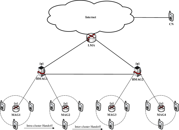
Overall CSPMIPv6 system architecture
-
Then the MAG i registers the MN in its domain cluster by sending a Local Proxy Binding Update (LPBU) to the HMAG j.
Upon the successful authentication by the HMAG j, the HMAG j registers the MN on the LMA by sending a Proxy Binding Update (PBU) including the MN-ID and the HMAG-ID.
-
Once the PBU message is received successfully by the LMA, a new Binding Cash Entry (BCE) is created to store the MN-ID and HMAG j identifier. Subsequently, the LMA sends a Proxy Binding Acknowledgment (PBA) reply to the HMAG j. The PBA message includes the Home Network Prefix (HNP) of the MN, which hereafter will be used for maintaining the MN reachability within the PMIPv6 domain. The LMA configures the routing path with the HMAG by setting a bi-directional tunnel between them to send and receive the traffic.
-
The HMAG j adds the MN information to its Binding Update List (BUL) in order to register the MN and sends a Local Proxy Binding Acknowledgment (LPBA) message to the MAG i containing the MN prefix. Then, routing configuration is performed to make the MN accessible.
-
When MAG i gets the LPBA message from the HMAG j, its BUL will be modified by adding the MN and forward the HNP to the MN through the advertisement message. Now, the MN has the ability to send and receive traffic.

The MN information at the end of registration will be stored in the MAG i, HMAG j, and LMA tables as stated in the aforementioned registration operation. Furthermore, The HMAG j exchanges the MN information with the MAG i to perform a routing configuration for the MN. Thus, there will be no need for a bi-directional tunnel set up between the HMAG j and MAG i [19]. Moreover, the idea of integrating the AAA functionalities with the LMA functions proposed by [6] is reused in this CSPMIPv6 protocol to reduce the signaling cost during the MN registration.
The handoff procedure within the CSPMIPv6 domain functions is illustrated in Fig. 2 and deliberated as follows.

Handoff procedure in the CSPMIPv6 domain
When the MN decides to move from its serving network to another within the CSPMIPv6 domain, the MN movements could be either an intra- or inter-cluster handoff. In the intra-cluster handoff, the MN is supposed to move to another MAG within the same cluster domain. In other words, the MN movement is still controlled by the same cluster head HMAG. Therefore, the handover here is performed by the HMAG through updating its binding table without any intervention from the LMA. To do so, the destination MAG to which the MN decides to move, will send an LPBU message to the respective HMAG including the MN-ID. Here, the HMAG will only need to update its table by setting the new MAG address in its MAG field as opposed to the inter-cluster handoff. This is done once the MN information has already been recorded. Then, the respective HMAG sends back an LPBA message, including the HNP to the requesting MAG as well as configures the routing performed with the requesting MAG in order to forward the MN packets.
In the inter-cluster handoff, the MN movement is detected by another MAG located outside the cluster domain of the serving MAG. Thus, when the destination MAG accepts to register the MN, an LPBU message is sent to the respective HMAG including the MN-ID. However, the HMAG will not find the MN-ID in its binding table as the MN comes from another cluster. Therefore, the LMA must be involved in the process. This is done by the requesting HMAG sending a PBU message to the LMA advertising the new location of the MN. Subsequently, the LMA will update its BCE tables and send a reply to the requesting HMAG.
Once the requesting HMAG receives the PBA, a new binding table for the MN will be created and a reply will also be sent to the respective MAG. Finally, a new entry for the MN will be created by the MAG in its binding table and an HNP message will be sent to the MN.
The CSPMIPv6 has gained several substantial benefits as a result of dividing the PMIPv6 domain into sub-local networks. These advantages have increased the MN user performance concerning the mobility management. This performance enhancement comes as a result of reducing the LMA load by relieving it from the local mobility signaling within the HMAG cluster. Furthermore, the signaling cost has been reduced as a result of integrating the AAA functionalities with the HMAG. Another critical benefit is shortening the routing path when the MN moves inside its cluster (i.e., intra-cluster handoff) while performing the handoff process by the HMAG without any involvement from the LMA. Despite all of these merits mentioned above, the CSPMIPv6 still suffers from several issues such as the one point of failure (single LMA), end-to-end delay, and excessive signaling [3].
3 Related works on PMIPv6 protocol load balancing mechanisms
In the PMIPv6, the mobility-related signaling responsibility is undertaken by the MAGs on behalf of the MN. All the MNs must be connected to a particular MAG which makes the MAG overloaded easily. The overloading on the MAG leads to an increase of packet loss, end-to-end delay, and the decrease of the transmission rate. Consequently, several works have been proposed to reduce the load on the overloaded MAGs via applying the load sharing mechanism between the MAGs to avoid the negative effect on the overall system performance.
Kim and Lee [14] propose a load-balancing mechanism to equitably distribute the load among different MAGs within the PMIPv6 domain. The proposed work led to improving the overall system performance in terms of average queuing delay, packet loss, and end-to-end delay, while increasing the transmission rate. The authors utilized the heartbeat message in order to allow for a specific MAG to learn the load status of its neighboring MAGs. The heartbeat message is modified in order to store the load field for the load balancing action. Similarly, the MAGs also sends a heartbeat message to the LMA, including their load status. The LMA stores the received loads in its BCE used to measure the overall system performance. The description of this is shown in Fig. 3. When the LMA load exceeds a specific threshold, a heartbeat message is sent by the LMA to the overloaded MAG. Then, the overloaded MAG performs a load balancing and chooses the MNs that have the option to change their point of attachment. The target MAG is selected by the serving MAG based on the received signal strength (RSS) and the load status reported from the MNs. The signaling process that is performed during the load balancing action is presented in Fig. 4. This work restricts the procedure of choosing the handover MN (HMN) for the handover process by preventing the serving MAG to select the MNs that have a real-time session. Numerical and simulation analysis has been conducted by the authors to evaluate their proposed mechanism, and their result shows significantly enhanced performance over the original PMIPv6. The abovementioned mechanism forms the core of the proposed LB-CPMIPv6 mechanism. Furthermore, all the paper variables and assumptions are also reused in this work to create an identical platform for comparative purpose.

Load balancing operation in the PMIPv6 domain [13]

Load balancing signaling in the PMIPv6 domain
Another work in this area has been done by Kim and Lee [13, 15] to enhance the load balancing by utilizing the IEEE 802.21 standard. The IEEE 802.21 optimizes the handover between the heterogeneous technologies via facilitating media-independent handover by providing up layers with network-related information. This work aims to determine the load on a candidate point of attachment (PoA). There are cases where the PoA suffers from heavy loads as compared to the TMAG that experiences a lower amount of load. This happens if the MAG load concentrates on only one of its PoA (BS/AP). Thus, the target PoA load is very important to knowing to reduce the overall load overhead. This proposed technique has proven to have a remarkable enhancement in terms of queuing delay and transmission rate.
Another load balancing approach has been proposed by Kong et al. [16] for efficient migration of the load between the MAGs. Their approach determines the target MAG which needs a low signaling requirement. Each MAG learns the load status of its neighboring MAGs by exchanging their load among each other in the domain. Then, the MAGs create a list of candidate MAGs based on the received load information in order to select the best TMAG for the HMN. A proactive load balancing is performed during the initial attachment of the MN by selecting the MAG that has the lowest load according to the load information. This is done before the current MAG becomes overloaded. Therefore, by avoiding the overloaded MAG, benefits such as low packet loss and low signaling will be achieved. However, in this mechanism, the HMN experiences an extra delay, especially in the proactive scenario caused by the time needed by the serving MAG to determine the best TMAG to which the HMN moves according to the MAGs loads. Real-time sessions have not been considered in [16], which in turn degrades the system performance. Moreover, this mechanism requires MNs with multi-interface to be connected with two different networks, which makes it restricted to this scenario. Also, multi-domains within the same domain has not been considered in this work, which makes the MN moves to a different domain that requires extra signaling, which in turn leads to high queuing delay and low transmission rate.
An agent-based scheme was proposed by Dimple and Kailash [17] to mitigate the overloaded MAG issue within the PMIPv6 network. Their mechanism works by moving the mobile agent from one location to another to reduce the load on the overloaded MAG. The mobile agent achieves this through visiting one MN to collect its data and moves to the other MNs associated to the MAG to take the only relevant data for transmission, in order to reduce the overhead communication. The MN selection is performed according to certain criteria such that the MNs that have real-time session will not be selected, while the MNs that have high-rate data connection become a target for a handoff. Despite the benefits gained by employing the MN agent, several issues arise. Anticipating the MN in the load balancing adds some burden to the MNs and increase the function complicity. This is done by selecting one MN to visit the other MNs within the MAG domain to collect the similar data packets which require some signaling messages between the MN and the associated MN. Moreover, the employed θ threshold by the LMA in the mechanism depends on the size of the data reduction by the MAG that sent to the LMA. This leads to overload the MAG that has numerous attached MNs but does not have any similar data between them or have less than the specified threshold, which not reflect the reality load state of the MAG. Furthermore, clustered PMIPv6 protocol not considered in their implementation, which in turn may lead to effect the intra-domain mobility advantages in a contrary manner.
Qutub and Anjali [18] introduce an efficient mechanism to balance the load among the overloaded and low-load MAGs. Their mechanism selects the target MAG according to its geographical serving area and its current load. Also, the MN selection for handover is performed based on the MN’s QoS profile, location, direction, and multi-interface capability. This selection has proven to reduce the overload and provide the service, which satisfies the QoS. In this work, not only the overloaded is avoided but also the services are provided with a level of QoS that satisfy the mobile users. However, employing the Global Position System (GPS) expedites the power of the MNs, which is not acceptable in the critical applications. Besides, this work consecrates on the overloaded MAGs and ignore the overloaded LMA. The overloaded LMA is determined according to the all MAGs load in the system, which may be accrued even when the MAGs are not overloaded. This definitely degrades the overall system performance through increasing the time of registering/de-registering the MNs (large queuing delay). Furthermore, divided domains do not consider in their work, which affects the QoS regarding the mobility management.
The load balancing problem also has been researched by the Internet Engineering Task Force (IETF) and for which a Request for Comments (RFC) was introduced by Jiang [20]. Each MAG sends its load periodically to the LMA and hereafter is used by the LMA to create a list of candidate MAGs for performing load balancing. The factors have been used in their mechanism to select the target MAG are specified in [18]. The process of selecting the HMN is performed as follows:
-
1.
When the MAG becomes overloaded, the MAG starts load balancing action by selecting the HMN according to its service type to avoid selecting the MN that has a real-time session.
-
2.
Then, the MAG sends Load State Message (LSM) to the LMA in order to inform the LMA about its loads.
-
3.
Accordingly, the LMA gives a feedback to the MAG about the overloaded MAGs and the non-overloaded MAGs. This is done by sending a Load State Acknowledgment Message (LSAM) to the MAG in order to migrate the HMN to a new MAG that is not overloaded.
-
4.
Once the MAG receives the LSAM message, it sends a request message to non-overloaded MAGs.
-
5.
The non-overloaded MAGs upon receiving the request messages reply to the requested MAG along with the acceptance or the rejection of its request according to their status.
-
6.
Then, the overloaded MAG sends a notification to the HMN including the information about the TMAG.
-
7.
The MN once receives the notification from the MAG, it sends Router Solicitation (RS) message to the TMAG to inform it about its movements.
-
8.
A PBU and PBA messages are exchanged between the MAG and the LMA to register the handoff MN.
-
9.
Finally, the TMAG sends a Router Advertisement (RA) message to the HMN including the new IP addresses in order to complete its registration.
According to the registration procedures in this mechanism, the MAG should send a request to the all non-overloaded MAGs and await their responses to select the TMAG for the HMN based these responses. This process consumes the bandwidth due to the messages exchanged between the MAGS during the load balancing mechanism. In addition, this work does not target the overloaded LMA, which is responsible for the acceptability of all the MNs connected to the MAGs that may be overloaded. Moreover, the intra domain mobility in case of dividing the PMIPv6 into sub-local domains is not considered, which lead to long handoff delay through increasing the path recovery and signaling cost.
Nguyen and Bonnet [21, 22] introduce a solution mechanism to solve the issue of load balancing in the PMIPv6 by considering the IP multicast session. Their solution caters two scenarios, which are named as proactive-multicast and the reactive-multicast. For the former, when the MN starts a new multicast connection, a load balancing action will be triggered to select the suitable LMA to manage this connection. However, in the latter, when the LMA becomes overloaded, the LMA starts to select some of the multicast sessions for a load balancing purposes. Then, the LMA selects the suitable target LMA for these sessions according to same criteria as specified in [21]. Their experiments and numerical results that have been conducted have shown significant improvements in terms of load distribution as well as reducing the multicast service disruption. However, moving the MN’s multicast session to another LMA (LMA has least load), which may be located far away from the MN affects the system performance. This is due to the long path between the MN and the new LMA that leads to long delay or packets drops high signaling cost. Moreover, this work focuses on balancing the load between the LMAs and ignores the overloaded MAGs, which may overload even when the load on LMAs is balanced.
Another work focuses on distributing the load between the LMAs introduced in [23]. The primary aim of this work is moving the load from the overloaded LMA to the LMA has the least load. This is done when the load at LMA reached the specified threshold. Accordingly, the LMA sends load balancing (LB) warning to the MAG that serves the selected MN. Then, the MAG sends refresh binding to the LMA and hereafter the LMA communicates with the new LMA to bind the selected MN to another LMA. Now, the MN anchored at the new LMA. This work shows remarkable improvements regarding the blocking probability and dropping probability than PMIPv6 with no load control. However, the authors do not take into consideration the overloaded MAG, which is easily susceptible to be overloaded any time when the attached MNs very high or when the MN requires a high stream session. This leads to service disruption through increasing the queuing delay. In addition, the hierarchical domain is not considered also in their work, which may lead to high queuing delay.
A load balancing scheme is introduced in [24] to improve the overall system performance in terms of handoff delay and throughput. The IEEE 802.21 Media Independent Handover Services (MIH) functionalities are utilized with the proper selection of the MN new network to provide a seamless handover in the heterogeneous networks. In this scheme, when the signal of the MN becomes very weak, a report from MN is sent to the MN serving MAG. Then, the PMAG upon receiving the report sends handover initiate (HI) message to the LMA including all candidates MAG/APs information. Accordingly, the LMA forwards the HI message to the candidates and these candidates response to the LMA with sending a Handover Acknowledgment (HAck) messages to inform the LMA about their status and their acceptance to serve the MN. The LMA forwards the received HAck messages to the serving MAG in order to select the proper network for the MN. Despite the enhancements that are made in this scheme regarding the handover time and throughput, additional signaling messages are required between the PMAG, LMA, and the candidates MAGs/APs, which negatively impact the system. The reactive load balancing is not considered in this scheme, which leads to increasing the blocking probability in the overloaded MAGs and service disruption due to increasing the queuing delay in the overloaded MAGs, in addition to ignoring the divided domain as the previous works do.
Raza et al. [25] employ the Software Defined Networking (SDN)-based solution in order to mitigate the loads between the LMAs. This works depend on central mobility controller that is responsible for monitoring the load at the LMAs. The controller upon detecting the load crossing over the predefined threshold on any of the LMA starts moving some traffic from the massive LMA load to the lower LMA load. According to the analytical analysis, their scheme has significant improvements regarding disruption period of uplink and downlink traffic during load balancing action compared to their benchmark. However, adding extra element is costly. In addition, the massive MAG load is not considered in their scheme, which affects the system performance in terms of handover delay. Moreover, LMA domains also not consider in this scheme, which leads to moving the track to another LMA located far away from the serving LMA. Furthermore, scalability issue has arisen as a result of using a central controller.
SDN also used by [26] to reduce the blocking probability and increase the resource utilization through using mobility-aware load distribution for multiple controllers. The objective of this work is handling the handover messages as fast as possible. This is performed by distinguishing the handover messages (gives them high priority) and manipulate them by the controller has the least load among the other controllers if the serving controller suffers from heavy load. However, the main consideration is given to the loads on the LMA and is ignored the loads on the MAGs. In addition, the clustered domain also is not considered in their scheme. These ignoring lead to serious issues regarding the mobility, which in turn affect the service delivered to the mobile users.
The review of these deliberated algorithms raises some major concerns which have to be considered for the load sharing mechanism. A list of candidate MAGs to be created with a fewer message exchange to avoid the network overloading issue and choosing the HMNs should be performed based on their traffic type to avoid the selection of the HMNs that have an arguing critical-session. Unfortunately, proposed works above metioned have not proposed such solution for the clustered-based protocol during the formation of the candidate MAG list. Thus, is effected the overall system performance as the selection of TMAG from another cluster or in the case, there is another target MAG from the same cluster of the serving MAG. Thus, this work has been motivated by these open issues focused on the clustered protocol and to provide solutions.
In this work, the CSPMIPv6 protocol is implemented to make it as the central referral platform for the proposed LB-CPMIPv6 mechanism. The proposed mechanism in [13] has been implemented in this research work whereas it is applied on the CSPMIPv6 for a comparison purpose. The CSPMIPv6 architecture is shown in Fig. 1. This protocol divides the PMIPv6 domain into sub-domains. Each domain encompasses some MAGs that form a cluster within the PMIPv6 domain. Subsequently, each cluster elects one MAG to act as the cluster head (HMAG). The MAG in the CSPMIPv6 can be easily overloaded as in PMIPv6 protocol. Figure 5 shows an example of the CSPMIPv6-based inter-architecture of its overlapped area among its clusters. The overlapped area between the sub-domains contains a number of HMN candidates. These candidates must have another optional network to connect with for the handover purpose. As seen in Fig. 5, MAG1 and MAG2 are located in the same cluster as the HMAG1, while MAG3 is located in a different cluster HMAG2. The solid lines represent the current connection of the HMN candidate, while the dotted lines represent the optional connection for it. The selection process of TMAG and HMNs must be performed to provide better performance to the HMNs. Likewise, choosing the appropriate network for the HMNs in the overlapped area leads to the balance of load between the MAGs, which in turn avoids the overlapped MAGs. The proposed enhanced load balancing algorithm is presented in the next section.

An example of CSPMIPv6 inter-structure for load balancing movement
4 The proposed LB-CPMIPv6 mechanism
In this paper, a new mechanism, named LB-CPMIPv6 is proposed to enhance the overall system performance of IP-WSNs by considering a load balancing approach in the clustered network. The proposed LB-CPMIPv6 mechanism expands the MAG capability to avoid overloading issue by developing a new load balancing mechanism. In addition, the proposed mechanism reduces the time needed to recover path between the communicating entities.
In the proposed LB-CPMIPv6 mechanism, a domain number should be assigned to every sub-domain in order to distinguish between the clusters within the PMIPv6 domain. The proposed LB-CPMIPv6 mechanism provides an efficient way to balance the load between the MAGs, by predicting the proper TMAG to which HMN moves accurately, as illustrated in Algorithms 1, 2, and 3. Algorithms 1, 2, and 3 explain the functionalities of MAG, HMAG, and LMA respectively within the proposed mechanism. The control flow diagram of LB-CSPMIPv6 mechanism is illustrated in Fig. 6.

Load balancing operations within CSPMIPv6 domain


4.1 Load balancing mechanism for clustered PMIPv6 domain (LB-CPMIPv6)
In this proposed mechanism, a load balancing mechanism is developed for a cluster PMIPv6 to improve the efficiency of MNs and accordingly the overall system performance is improved. This is due to the need to take into consideration the intra- and inter-domain mobility during the load balancing process. The MAG located within the CSPMIPv6 domain acts as the gateway between the MNs and the HMAG. Thus, the MNs must be connected to the MAG to be connected to the network. Subsequently, the MAG could become overloaded if the number of the connected MNs increases in the network. This constraint has motivated, a new load balancing mechanism, which is applied to reduce the load at mainly the overloaded MAGs.
In order to ensure the standardization of the performance analysis as a comparative platform, the LB-CPMIPv6 mechanism performance analysis has reused the parameter values and assumptions that have been presented by Kim and Lee in [13]. Hereafter, the proposed load balancing mechanism for the PMIPv6 network in [13] should be referred as the “LBM-PMIPv6 mechanism” for the sake of simplicity.
In the CSPMIPv6 system model, the load at MAG i is measured according to the average packet arrival rate in a particular interval time. The similar measurement is used for measuring the arriving rate at a certain jth time interval and will hereafter be denoted by λi where the Nm is the number of the measurements. The Nm measurements are used to estimate the \( \bar {\lambda }\) for MAG i, which is computed as the average arrival rate at a certain time interval. After that, the MAG i calculates the average packet arrival rate using the weighted moving average technique under the assumption that μi is the average service rate of the MAG i, which is used by [13] and is mathematicaly expressed as follows:
The reason to utilize the weighted moving average method is to reveal the uncontrolled action. In addition, it gives a higher weight to the current traffic sample as compared to the old traffic sample in the measurement as proposed in [27] in order to compute the MAG load precisely. Then, the pi can be expressed as \( \frac {\bar {\lambda }_{i}}{\mu _{i}} \) where the \( \bar {\lambda } \) is the average arrival rate and the μi is the average services rate at a certain time. By considering the MAG i processing capacity into account, θi is the maximum acceptable load on the MAG i. If pi>θi, MAG i becomes overloaded and will perform a load balancing technique.
In the LB-CPMIPv6 mechanism, every MAG is supposed to send its load and its domain number in a periodical manner to the related HMAG using the heartbeat message, which has been introduced in [28]. The heartbeat message is exchanged periodically by the MAG information related to their related HMAGs within the CSPMIPv6 domain. This is done to inform the HMAGs with their loads as well as to detect the reachability of the other end links. In this work, the heartbeat message is extended to include the load status and the domain number, as shown in Fig. 7. In addition, the Proxy Binding Acknowledgment (PBA) and the Local Proxy Binding Acknowledgment (LPBA) messages, which are presented in [2] and [4] respectively are extended, as shown in Figs. 8 and 9. This extension is to include the domain number during the initial attachment of the MAGs while in the other control signaling the domain number is set to be zero. These two mechanisms are used to define the domain numbers, which are dynamically done by the LMA according to the number of its related domains or statically done during the installation.

Heartbeat message, including the domain number

PBA message, including the domain number

LPBA message, including the domain number
Each domain number and loading information that is received by the HMAGs, LMA, and MAG are saved in their databases, which are then used in the intra- and inter-domain load balancing. Subsequently, every HMAG k also measures its load status, F1, via employing the stored load information on its database that is received from its related MAGs within its domain. The total load for each HMAG domain pt can be expressed as \(p_{t} = \sum _{i=1}^{M} p_{i}\) where the M is the number of the MAGs within the HMAG k domain in the CSPMIPv6 domain. If pt>θ, the HMAG k measures the Fairness Index (FI) according to the Eq. 2 that is given by [29]. The FI lies between 0 and 1. If all the MAGs within the HMAG k domain have the same load, the FI is 1.
Subsequently, the HMAG k uses the MAGs load information, which is stored in its policy database to compute the f value and the compares it with θf. If f <θf, the HMAG k will send a heartbeat message to its related MAGs to inform the most overloaded MAGs to perform a load balancing action. In this work, the extended field (F flag and load status field) in the heartbeat message that is given by [13] is reused in the same way.
Finally, every HMAG in the CSPMIPv6 domain has to send its load that is received from the related MAGs to the LMA. This is performed using the heartbeat message to compute the overall system performance and operates as follows.
Once the HMAG receives the total loads pt from each related MAGs, the HMAG send these loads to the related LMA periodically using the heartbeat message.
Upon receiving the pt loads from the associated HMAGs, the LMA computes the load status F1, using the received loads to measure the overall system performance within the CSPMIPv6 domain. The total load can be expressed as:
where the N is the number of the HMAG in the CSPMIPv6 domain and pt is the total load at the HMAG k. After that, the LMA in the CSPMIPv6 domain measures the F1 according to the MAGs load received by the related HMAG in the entire system as expressed in Eq. (2), where M denotes the number of HMAGs in the system.
If f is less than θfL, a heartbeat message request is sent by the LMA to the most overloaded HMAGs to inform them to perform a load balancing action. The LMA uses the received loads from all the related HMAGs to determine the most overloaded HMAGs. A new flag is also added to the heartbeat message is named F and is set to 1 if the heartbeat message comes from the LMA entity to the related HMAGs or zero if the heartbeat message comes from the HMAG to the related MAGs.
Once the overloaded HMAG receives the heartbeat message, a load balancing action is performed by sending a heartbeat message to the related MAGs, which in turn selects the HMNs in the overlapped area. The HMNs must change their point of attachment to another MAG. The criteria of the HMN selection are discussed in the next subsection.
According to the above explanation, the LB-CPMIPv6 mechanism only affects the protocols with multiple domains. In other protocols, there is no impact because the LB-CPMIPv6 mechanism deals with the whole domain as one domain. Thus, selecting the MAG will be performed based on the LBM-PMIPv6 mechanism [13].
4.1.1 HMN selection
The wrong selection procedure of the HMNs candidate significantly degrades the performance of the system. Thus, the system must be adapted to appropriately choose the HMNs in a better manner. In this work, the process of HMNs selection by the overloaded MAG is performed based on some criteria as follows.
The MAG chooses the HMN that has an option to change its connection. This indicates that the HMN is located between different networks that are advertising their services to such HMN in order to maintain a continuous IPv6 session. This is achieved if the HMN is located in the MAGs overlapped area and it receives a Signal Strength (SS) from all of them.
The MAG creates a candidate list for the HMNs that exist in its overlapped and receive an RSS from another MAG.
Then, the MAG should select the HMNs that require the highest data rate from the candidate HMNs.
The MAG should not select the HMNs that have a real-time connection (e.g., audio and video) due to the sensitivity to delay leading to increase the handoff latency.
To determine the non-real HMN session by the MAG, the “Traffic Class” or the “Flow Label” field of IPv6 must be examined by the MAG for all the candidate HMNs in the MAG overlapped area [30]. So disturbing the real-time session during the handover latency will be avoided. If the MAG overlapped area does not contain any non-real HMN session, the HMNs with the highest data rate will be selected.
After the HMNs selection by the MAG from its candidate list, the MAG now is ready to choose the best target MAG to where the HMNs bind. The selection of the target MAG is performed as described in the subsection of the target MAG selection.
4.1.2 Target MAG selection
For an enhanced load distribution, the selection of the target MAG must be performed as accurately as possible. Therefore, the Technique for Order Preference by Similarity to Ideal Solution (TOPSIS) algorithm is modified to determine the target MAG in this research. Furthermore, in this study, additional operations are proposed to adopt the algorithm with the clustered PMIPv6. The intra- and inter-cluster handoffs within the CSPMIPv6 domain have been considered due to the adaptation process. The system has achieved better selection technique to the target MAG among the candidates MAGs, which have been reflected in the system performance in terms of handover latency, end-to-end delay and queuing delay as presented in Section 6. The enhanced processes of selecting the best target MAG are performed as follows:
The MAG utilizes the RSS, which is reported by the HMN to determine the available network for the HMN.
The MAG then places the available networks as candidate networks (i.e., candidate MAGs). This is performed to select the best candidate MAG in terms of RSS, load status and the domain number during the load balancing action. The technique for order preference is adapted from the TOPSIS algorithm that is presented in [27]. The TOPSIS algorithm is used by the serving MAG to determine the target MAG. This algorithm used to choose the optimal MAG as possible according to the Signal Strength reported by the HMNs and the load status of that MAG. Observation shows that the TOPSIS algorithm is not suitable when applied within the clustered PMIPv6 domain. This is due to the fact of dividing the domains into local sub-domains, which is not considered in the TOPSIS algorithm, subsequently increasing the communication overhead. Therefore, some enhancement has been implemented by the LB-CPMIPv6 mechanism starting with modification of the exchanges of messages between the system entities until of change the HMN its points of attachment to ideal TMAG. The TOPSIS algorithm steps including the additional operations of selecting the optimal target MAG for the HMNs are described as follows:
Step 1: The TOPSIS algorithm constructs the decision matrix D, which is a [1×n] matrix, as:
where Ci represents a pair of pi and Si for the ith candidate MAG in the matrix D, as:
where pi denotes the load status and Si represents the signal strength of candidate MAG i and n is the number of candidate MAGs in the matrix D. Moreover, the TOPSIS algorithm is designed to avoid the candidate MAGs, which load is more than a predefined threshold θ.
Step 2: The TOPSIS algorithm computes the normalized decision matrix \(\bar {D}\), which is a [1×n] matrix, as:
where \(\bar {C}_{i}\) represents a pair of \(\bar {p}_{i}\) and \(\bar {S}_{i}\) for the each candidate MAG in the matrix \(\bar {D}\), as:
where \(\bar {p}_{i}\) = \(\bar {p}_{i}\slash {\sum \limits _{i=1}^{n} \bar {p}^{2}_{i}} \) and denotes the value of normalized load status, while the \(\bar {S}_{i} = {\bar {S}_{i}} \slash {\sum \limits _{i=1}^{n} \bar {S}^{2}_{i}}\) and represents the value of normalized signal strength of candidate MAG i and n is the number of candidate MAGs in the matrix \(\bar {D}\).
Step 3: The TOPSIS algorithm uses the weight value (w), which is a system parameter. This weight (w) and its complement to 1 (1−w) are used to weight the pi and Si, respectively. Since the load at the candidate MAG (pi) has higher priority than the signal strength (Si), the weight value (w) have to always be greater than 0.5.
Step 4: The TOPSIS algorithm calculates the weighting decision matrix: V, as:
where \(w\bar {C}_{i}\) represents a pair of \( w\bar {p}_{i}\) and \(w\bar {S}_{i}\) for the each candidate MAG in the matrix \(\bar {D}\), as:
where the \( w\bar {p}_{i} \) is the result of the multiplication of the weight value with the normalized load status value and the \( w\bar {S}_{i}\) is the result of the multiplication of the weight value with the normalized signal strength. For the sake of simplicity the \( w\bar {p}_{i} \) is replaced by vp, where the \( w\bar {S}_{i}\) is replaced by vS
Step 5: Determine the optimal network C∗ (min vp, max vS and the worst network \( \hat {C} \) (max vp, min vS) from V matrix:
Step 6: The TOPSIS algorithm calculates the separation measures by using the Euclidean distance. The separation of each candidate MAG from the optimal and the worst MAG, S∗ and \( \hat {C} \) are calculated as:
Step 7: Next, the MAG ranks the preference order after calculating the relative separation measure as:
Step 8: This step is performed according to two different cases. First, if the closest MAG to the ideal network environment has the same domain of the serving MAG, the serving MAG selects it without any hesitation as the target MAG. Second, if the closest MAG to the ideal network is from a different domain, the serving network looks into the ideal network candidate MAGs list to see if there is another ideal one has the same domain in order to choose it instead of the ideal one has a different domain. The selection of the TMAG from the ideal network candidates maintains the system stability in terms of signal strength and the load status. This means, the process of selecting the TMAG that have the same domain will not affect the thresholds of the signal strength and the load, which will lead to the maintenance of the connection session without any service disruption.
Step 9: When the serving MAG has done the selection of the closest MAG to the ideal network environment from the ranking preference, the serving MAG starts a load balancing process by sending a handover command message to HMN. In order to select the ideal TMAG, a new load balancing signaling is proposed. In the next section, the new load balancing signaling within the clustered protocols is explained in detail.
5 Load balancing signaling for the clustered PMIPv6 domain
As mentioned earlier, every MN within the PMIPv6 domain must connect to a particular MAG to communicate with other MNs. This can lead to overloading the MAG, especially in large networks, when the number of MNs is substantial. This section presents the required signaling of our proposed work to mitigate the load of the overloaded MAG. Figure 10 shows that this signaling is extended from the CSPMIPv6 signaling framework, which includes the inter- and intra-handover signaling operation [4]. Given that, the MN sends a report to the serving network, which includes the MN-ID, MN-IID, the new MAG-ID, and the RSS. This report is sent only if the RSS exceeds a threshold as performed in Third Generation Partnership Project (3GPP). The scenario of performing a load balancing handover in the clustered PMIPv6 domain is performed as follows.

Load balancing signaling in the CSPMIPv6 domain
The MAG i performs a load balancing procedure according to three cases. Therefore, when a load of MAG i exceeds a specific threshold or if its cluster head HMAG j sends a load balancing request or if the LMA orders the HMAG j, to perform a load balancing, which in turn moves this order to the related MAG i. After that, the MAG i starts to perform a load balancing procedure by choosing the appropriate HMN from the overlapped area to perform a handover action. This HMN selection is performed as presented earlier.
When the MAG i receives the handover report from the HMN, the MAG i extracts the IDs of the candidate MAGs, which is given by the report and subsequently stored as a list on its policy database. Then, the MAG i utilizes the Handover initiates (HI) and the Handover Acknowledgment (HAck) messages, which are introduced by [11] and extended by [13] to determine the load of the candidate MAGs. This is done by sending an HI message by the MAG i to all candidates MAGs including the MN-ID. Once the HI message received by the candidate MAGs, the candidate MAGs reply by sending HAck messages emulated to the MAG i including the current loads information. A flag N used as introduced by [13] to distinguish between the HI and HAck messages.
The MAG i employs the received loads information from the candidate MAGs and the domain number to choose the TMAG, which the HMN will move to as described in Section 2.2. Subsequently, a Handover Command Message (HCM) is sent by the MAG i to the HMN.
Upon receiving the HCM, the HMN starts a new link connection with the TMAG.
When the TMAG detects the attachment of the HMN, an LPBU message sends to the HMAG k.
Once the HMAG k receives the LPBU message, the HMAG k fetches its binding table by searching for the HMN information. If the HMN moves to another MAG within the HMAG k cluster domain, which is as called intra-cluster handoff mobility, the HMAG k updates its Binding Cash Entry (BCE) by setting the New MAG (NMAG) address instead of the TMAG address in its MAG field. On the other hand, if the HMN moves to another MAG in a new HMAG (NHMAG) cluster domain within the CSPMIPv6 domain, which is as called inter-cluster handoff mobility, the NHMAG will not find any matching entry in its BUL table. Since the HMN comes from another cluster, so the NHMAG sends PBU to the LMA to update its BCE for the HMN. Then, the HMAG field entry in the BCE of the LMA will be modified by setting the NHMAG address and releases the old one for the HMN. After that, the LMA replies to the NHMAG via sending a PBA message.
The NHMAG, upon receiving the PBA message sends an LPBA message to the NMAG after updating its binding entry for the HMN.
The NMAG consequently updates its BUL for the HMN and advertises the HNP to the HMN.
6 Performance evaluation
This article presents the development of a load balancing mechanism among MAGs in the CSPMIPv6 domain. The performance analysis of this algorithm and the comparative analysis has been done using discrete event simulation and in particular the NS2. For the evaluation purposes, the work in [13] is re-implemented and the CSPMIPv6 protocol, which is presented in [4]. Also, this work reuses the parameter values and assumptions that have been used in [13] to ensure a level of comparative platform, as shown in Table 1. Table 1 shows the new setup values needed by LB-CPMIPv6 mechanism for performing load balancing. In addition, the performance gain is calculated as in [31] to show the variation results between the proposed LB-CPMIPv6 and LBM-PMIPv6 mechanisms based on Eq. (13), where x and \( \acute {x} \) represent the results produced using LB-CPMIPv6 and LBM-PMIPv6 mechanisms respectively.
6.1 System setup
This section illustrates the simulation setup used in the experiments in order to evaluate the proposed load balancing mechanism. The experiments are performed using the network simulator NS2 [32, 33]. As illustrated in Fig. 11, which represents the system topology, the MNs communicate with each other including the CN that is connected to the CSPMIPv6 domain through the core network. The Poisson process has been used by CN and MNs to generate packets with a mean rate of 2 packets/ms. Each MAG measures the packet arrival rate (λ) at every 50 ms. When the number of measurements reaches 20 times by the MAG, the MAG calculates the \( \bar \lambda \) using the weighted average method as depicted in Eq. (1). In the proposed network topology, the MNs are randomly scattered over 10 MAGs. In addition, the MAGs are equally connected with two HMAGs (HMAG1, HMAG2) while the HMAGs are associated to one LMA. The load status for each MAG is carried by the heartbeat message that is sent every single second to their related HMAG. The time between the first Heartbeat and the next should be small as recommended in [28]. Similarly, the HMAGs send their load status to the LMA to measure the overall system performance. Several MNs are scattered randomly over the MAGs areas. The total load varies between 0.05 to 0.8. Every MAG is associated with a limited queue K as mentioned in Table 1. For simplicity, each MAG in the network topology is considered to have same service rate μs and a threshold value θs. The simulation is conducted under three different scenarios. In the first scenario, the LB-CPMIPv6 mechanism is applied in the PMIPv6 network (without-clustering) and is compared with LBM-PMIPv6 mechanism [13]. This scenario can show the impact of LB-CPMIPv6 mechanism in the PMIPv6 protocol that uses no clustering technique. In the second scenario, each MN can connect to one, two or three MAGs with an equal probability within the CSPMIPv6 domain. This scenario is performed to inject the overlapped area with a high number of MNs in order to show the actual impact of the intra-cluster handoff process on the system performance. In the last scenario, each MN is connected to one or zero MAG with a probability equal and 0.2 and 0.8 respectively, without any concentration on the overlapped area between the MAGs.

The network topology used for simulation
6.2 Results and discussion
In this section, the performance metrics evaluated are the average queuing delay, handover latency, transmission rate and the packet loss. The queuing delay is defined as the summation of the waiting time of each packet in the queue per MAGs. The transmission rate is measured by calculating the average amount of data transmission from the MAGs for the entire simulation. Three scenarios are conducted to demonstrate the enhancement of LB-CPMIPv6 mechanism in the clustered protocol against the LBM-PMIPv6 mechanism in addition to the scenario situation of no load balancing. The scenarios have been conducted as follows.
In the first scenario, the proposed mechanism applied on the standard PMIPv6 protocol, which means that the MAGs belong to the same domain (no hierarchical domain). In this scenario, a comparison between LB-CPMIPv6 mechanism and LBM-PMIPv6 mechanism in PMIPv6 domain is carried out in terms of measuring average queuing delay. The result of this comparison is depicted in Fig. 12. As observed from the figure both, the LB-CPMIPv6 mechanism and LBM-PMIPv6 mechanism have achieved similar results in terms of average queuing delay, while PMIPv6 protocol, which has no load balancing mechanism, shows a higher average queuing delay. In the LB-CPMIPv6 mechanism, if there is only one domain (no clustering), the serving MAG selects the TMAG according to its load and based on RSS reported from HMN. In this case, the LB-CPMIPv6 mechanism works precisely similar to LBM-PMIPv6 mechanism, and PMIPv6 protocol shows the highest average queuing delay since it does not support the load balancing. Thus, the packet service time inside the overloaded MAG buffer increases as a result of traffic from connected MNs.

The average queuing delay per MAG in the PMIPv6 protocol
In the second scenario, Fig. 13 illustrates the average queuing delay per packet at the MAG versus the overall system load for the entire simulation time within a clustered environment. In this scenario, the CSPMIPv6 protocol is employed as an experimental environment to show the effectiveness of the proposed LB-CPMIPv6 mechanism in the clustered domain, which totally differs from the first scenario applied in the non-clustered domain. It is evident that the LB-CPMIPv6 and LBM-PMIPv6 mechanisms outperform the average queuing delay of the CSPMIPv6 protocol, which has no load balancing. Performing the load balancing action leads to the reduction of the packets buffering time at the overloaded MAGs. Furthermore, the performance for LB-CSPMIPv6, LBM-PMIPv6 and CSPMIPv6 shows same results regarding the queuing delay before the predetermined thresholds take place.

The average queuing delay obtained from scenario 2
When the system load reaches 0.105 and 0.175, the HMAG and/or the LMA starts to perform a load balancing action because the values in the figure are influenced after the predefined thresholds take place. In addition, when the total load reaches 0.35 for θf=0.5, a few MAGs suffer from the overload issue. Subsequently, the overloaded MAGs start performing a load balancing procedure as depicted in Fig. 13. The LB-CPMIPv6 mechanism shows identical results regarding the queuing delay in comparison to the LBM-PMIPv6 mechanism before reaching the respective thresholds. On the other hand, when the respective thresholds are reached, the average queuing delay increases whenever the load increases. This is due to the increase of the number of exchanged packets among the MNs. However, the LBM-PMIPv6 mechanism shows high queuing delay compared to LB-CPMIPv6 mechanism, as illustrated in Fig. 13. This is because sub-domains are not utilized in the clustered protocols, which affects the intra-cluster handoff. The performance gain of LB-CPMIPv6 mechanism over LBM-PMIPv6 mechanism is 15.66% on average.
The LB-CPMIPv6 mechanism selects the ideal MAG from the best candidates through employing the domain number, which in turn leads to shortening the time needed for delivering packets to their destination after the handoff. For example, when the load reaches 0.105 on the HMAG, the HMAG performs load balancing by sending a message to the overloaded MAG, which is located on its domain and each overloaded MAG selects the TMAG based on its load, domain number and the RSS.
Figure 14 illustrates the packet loss ratio between LB-CPMIPv6, LBM-PMIPv6 mechanisms and the CSPMIPv6 protocol. The advantages of applying the load balancing mechanisms in the protocols can be demonstrated clearly to an overall reduction in the overloaded MAGs. For example, the load balancing reduces the increased level of buffer utilization, which in turn reduces the number of lost packets. In addition, the LB-CPMIPv6 mechanism achieves better results in terms of packet loss as compared to the LBM-PMIPv6 mechanism. This is because the fact that the LB-CPMIPv6 mechanism moves the HMNs within the same domain as possible, which results to bring down the time of the handoff process leading to the reduction packet loss. In other words, shortening the time needed to perform the handoff process leads to the reduction of the packet waiting in the buffer, which in turn reduces the packet loss.

Number of packet loss for LB-CPMIPv6 mechanism, Kim and Lee [13] and non-load balancing
When the total load reaches 0.175, the LMA and a minimum one of the HMAGs exceed their thresholds, which are depicted in Table 1 (\( \theta _{f_{L}} \) and θ), and for that the balancing function will be triggered by LMA and/or the respective HMAG. The TMAG that has taken the same domain with the MAG that has load balancing action will be selected according to the MAG selection criteria in LB-CPMIPv6 mechanism. This definitely leads to shortening the time needed to register the HMN on the TMAG, which in turn decreases the packet waiting time in the queue. This enhancement leads to the reduction of the packet congestion from the point of view of the queuing system. Moreover, selecting the TMAG based on the RSS and load status only in the LBM-PMIPv6 mechanism increases the packet loss ratio. This is due to the long registration time that is needed to register the HMN in a different domain, which increases the buffering time. This results in the increasing of congestion from the queuing system perspective.
A related example to this is the movement of the HMN to another cluster domain causes an extra delay due to the time needed to exchange its information among the HMAGs. After this, this information should be emulated to the TMAG, which in turn needs a buffering technique to preserve the packets during the handover process.
Figure 15 compares the effects of LB-CPMIPv6 mechanism and LBM-PMIPv6 mechanism on the handover latency. The handover latency is the interval between the time of the last packet that is received by the HMN from the old path and the time of the first packet that is received from the new path by the HMN. The LB-CPMIPv6 mechanism outperforms the LBM-PMIPv6 mechanism in terms of the handover latency. This is due to that the TMAG is selected based on the domain factor. In other words, the time needed to perform a handoff process by the HMNs is reduced. This is done by eliminating the authentication process on TMAG and performing the handover without the involvement of the LMA, which may be located far from the HMNs. The handover process is performed by the overloaded MAG if the load in the LMA, HMAG or MAG exceeds their predetermined thresholds. As in Fig. 15, the handover is started, when the total load reaches 17.5 and is performed again when some MAGs become overloaded. The performance gain of LB-CPMIPv6 mechanism over LBM-PMIPv6 mechanism is almost 32.68%.

Impact of intra-cluster handoff on the handover latency
In the third scenario, the average queuing delay, transmission rate and end-to-end delay are measured, as shown in Figs. 16, 17, and 18 respectively.

The average queuing delay obtained from the third scenario

The transmission rate obtained from the third scenario

End-to-end delay per MAG versus the total load
Figure 16 depicts the impact of the LB-CPMIPv6 on the average queuing delay in comparison with the LBM-PMIPv6 mechanism and the original CSPMIPv6 protocol. The figure shows that the LB-CPMIPv6 mechanism increases the performance of the LBM-PMIPv6 mechanism even when the overlapped area is characterized by a small number of MNs. This can be attributed to the proposed mechanism performance to select the TMAG from the same domain when the overloaded MAG performs a load balancing action. This definitely leads to the shortening of the time needed to register and authenticate the MN on the TMAG, which in turn decreases the packet waiting time in the queue, especially in the limit queue. The performance gain of LB-CPMIPv6 mechanism over LBM-PMIPv6 mechanism is almost 9%.
Figure 17 shows the average data transmission rate from the MAGs per MNs in the third scenario. The MNs scattered randomly within the CSPMIPv6 domain. It is obvious that the LB-CPMIPv6 mechanism has a higher data transmission rate than the other mechanisms, while the CSPMIPv6 with no-load balancing has the least data transmission rate.
We observed from Fig. 17 that the data transmission rate is roughly stable in the LB-CPMIPv6 and LBM-PMIPv6 mechanisms. However, in the case of no-load balancing, the data transmission rate decreases whenever the MNs arriving rate increases. This is due to the absence of load balancing that leads to an unbalanced situation at the MAGs within the CSPMIPv6 domain. Furthermore, LB-CPMIPv6 mechanism shows a significant enhancement in data transmission rate compared to LBM-PMIPv6 mechanism, as shown in Fig. 17. This is due to the fact that the LB-CPMIPv6 mechanism gives higher priority for the selection of the TMAG based on its domain without affecting the load status or the SS threshold. This mechanism increases the traffic among the MAGs resulting in increasing the data transmission rate. Furthermore, forwarding the HMNs traffic to the TMAG that is located in the same cluster reduces the time needed for registering the HMN and authenticating it in the TMAG, which in turn increases the amount of sent packets to their targets. However, in the LBM-PMIPv6 mechanism, the traffic usually has an extra delay as a result of sending packets to another cluster.
Figure 18 presents the measured average of the end-to-end delay per MAG in the CSPMIPv6 versus the total load on the overall system. Interestingly, the LB-CPMIPv6 mechanism outperforms the LBM-PMIPv6 mechanism and the CSPMIPv6, which has no load balancing, despite reducing the overlapped area. This is due to performing load balancing action by the overloaded HMAGs, which leads to distribute the load within their clusters. This, in turn, leads to shortening the routing path as well as choosing the most closest MAG to the serving MAG. Selecting the TMAG based on its domain number has a positive impact on the overall system performance. Subsequently, the result shows that the utilizing domain number during the TMAG selection reduces the end-to-end delay due to the path faster recovery for the HMN after the handoff. Furthermore, the original CSPMIPv6 protocol has a higher end-to-end delay due to the unfair distribution of load. The unbalancing MAGs suffer from the heavy load, which in turn increases the overhead on the MAGs queue, causes extra packet time delay. Moreover, CSPMIPv6 tends to have relatively long paths, which also contributes to increasing the end-to-end delay.
7 Conclusions
PMIPv6 protocol and its extensions have been proposed to provide a seamless handover action within a localized management network. This is achieved via relieving the MN from any signaling-related to the mobility process when the MN changes its link. This is done by adding the new MAG that performs the mobility related-signaling with the LMA instead of the MN. Furthermore, the MAG establishes a tunnel with LMA to send and receive the packets of the MN. However, to establish a new link connection, the MN has to be associated with a specific MAG. This association could overload the MAG. Consequently, the LB-CPMIPv6 mechanism has been proposed in this article to fairly distribute the loads among the MAGs fairly. The main advantage of LB-CPMIPv6 is its capacity to consider clustered domain within the clustered protocols, which is not considered in other competitive mechanisms.
In the LB-CPMIPv6, the HMN that has a real-time session will not be selected during the process of the load balancing; this restriction relieves the critical applications from service disruption. Furthermore, the CSPMIPv6 handover signaling has been extended to be adapted with the newly proposed load balancing mechanism. Moreover, the LPBA, PBA, and the heartbeat messages are modified to enable sharing of the domain number for the new load balancing mechanism.
The LB-CPMIPv6 mechanism is implemented and simulated using the well-known NS2 simulator. The evaluation of the LB-CPMIPv6 mechanism in comparison to the LBM-PMIPv6 load mechanism and CSPMIPv6 protocol is performed in terms of queuing delay, packet loss ratio, end-to-end delay, and transmission rate. The results show that the new load balancing mechanism achieves a better performance by reducing the average queuing delay, packet loss, end-to-end delay, and increasing the transmission rate.
Change history
07 November 2018
Following publication of the original article [1], an error was noticed in the article. The third author’s name was inadvertently misspelled.
References
PCD Johnson, J Arkko, Mobility support in IPv6. Technical report, RFC 3775 (June 2004). https://www.rfc-editor.org/info/rfc3775.
ELKDVCKS Gundavelli, B Patil, Proxy Mobile IPv6. Technical report, IETF, RFC 5213 (2008). https://www.rfc-editor.org/info/rfc5213.
SM Ghaleb, S Subramaniam, ZA Zukarnain, A Muhammed, Mobility management for IoT: a survey. EURASIP J. Wirel. Commun. Netw.2016(1), 165 (2016).
AJ Jabir, SK Subramaniam, ZZ Ahmad, NAWA Hamid, A cluster-based proxy mobile IPv6 for IP-WSNs. EURASIP J. Wirel. Commun. Netw.2012(1), 1–17 (2012).
JH Lee, KD Singh, JM Bonnin, S Pack, Mobile data offloading: a host-based distributed mobility management approach. IEEE Internet Comput.18(1), 20–29 (2014).
MM Islam, E-N Huh, Sensor proxy mobile IPv6 (SPMIPv6)—a novel scheme for mobility supported IP-WSNs. Sensors. 11(2), 1865–1887 (2011).
MM Islam, S-H Na, S-J Lee, E-N Huh, A novel scheme for PMIPv6 based Wireless Sensor Network. Future Generation Information Technology: Second International Conference, FGIT 2010, Jeju Island, Korea, December 13-15, 2010. Proceedings (Springer, Berlin, 2010).
MM Islam, TD Nguyen, AA Al Saffar, S-H Na, E-N Huh, in Computational Collective Intelligence. Technologies and Applications: Second International Conference, ICCCI 2010, Kaohsiung, Taiwan, November 10-12, 2010. Proceedings, Part III, ed. by J-S Pan, S-M Chen, and NT Nguyen. Energy efficient framework for mobility supported smart IP-WSN (SpringerBerlin, Heidelberg, 2010), pp. 282–291. http://dx.doi.org/10.1007/978-3-642-16696-9_31.
H-N Nguyen, C Bonnet, in 2008 5th IEEE International Conference on Mobile Ad Hoc and Sensor Systems. Proxy mobile ipv6 for cluster based heterogeneous wireless mesh networks (IEEEAtlanta, 2008). https://doi.org/10.1109/MAHSS.2008.4660097.
AJ Jabir, S Shamala, Z Zuriati, N Hamid, A comprehensive survey of the current trends and extensions for the Proxy Mobile IPv6 Protocol. IEEE Syst. J.PP(99), 1–17 (2015).
CKKRPBH Yokota, F Xia, Fast Handovers for Proxy Mobile IPv6. Technical report, RFC 5949 (2010). https://www.rfc-editor.org/info/rfc5949.
MS Kim, S Lee, D Cypher, N Golmie, in Global Telecommunications Conference (GLOBECOM 2010). Fast Handover Latency Analysis in Proxy Mobile IPv6 (IEEE, 2010), pp. 1–5.
M-S Kim, S Lee, Load balancing and its performance evaluation for layer 3 and IEEE 802.21 frameworks in PMIPv6-based wireless networks. Wirel. Commun. Mob. Comput.10(11), 1431–1443 (2010).
K Mun-Suk, L SuKyoung, A novel load balancing scheme for PMIPv6-based wireless networks. {AEU} - Int. J. Electron. Commun.64(6), 579–583 (2010).
MS Kim, S Lee, in 2009 IEEE 20th International Symposium on Personal, Indoor and Mobile Radio Communications. Load balancing based on layer 3 and ieee 802.21 frameworks in pmipv6 networks (IEEETokyo, 2009), pp. 788–792. https://doi.org/10.1109/PIMRC.2009.5450177.
H Kong, Y Jang, H Choo, in Computational Science and Its Applications (ICCSA), 2010 International Conference On. An efficient load balancing of Mobile Access Gateways in Proxy Mobile IPv6 Domains (IEEEFukuoka, 2010), pp. 289–292. https://doi.org/10.1109/ICCSA.2010.67.
J Dimple, C Kailash, A load reduction and balancing scheme for MAG operating in PMIPv6 domain (Springer, Berlin, Heidelberg, 2013). http://dx.doi.org/10.1007/978-3-642-35864-7_19.
S Qutub, T Anjali, in Electro/Information Technology (EIT), 2012 IEEE International Conference On. Load sharing mechanism for Mobile Access Gateways in PMIPv6 (IEEEIndianapolis, 2012). https://doi.org/10.1109/EIT.2012.6220760.
F Teraoka, T Arita, in 2011 Third International Conference on Ubiquitous and Future Networks (ICUFN). PNEMO: a network-based localized mobility management protocol for mobile networks (IEEEDalian, 2011), pp. 168–173. https://doi.org/10.1109/ICUFN.2011.5949156.
H Jiang, Load sharing support for MAGs in Proxy Mobile IPv6. Technical report, IETF-Draft (expired) (December, 2011).
T-T Nguyen, C Bonnet, Considerations of IP multicast for load balancing in Proxy Mobile IPv6 networks. Comput. Netw.72(Supplement C), 113–126 (2014).
TT Nguyen, C Bonnet, in 2014 International Conference on Computing, Networking and Communications (ICNC). Load balancing mechanism for Proxy Mobile IPv6 networks: an IP multicast perspective (IEEEHonolulu, 2014), pp. 766–770. https://doi.org/10.1109/ICCNC.2014.6785433.
S Jeon, RL Aguiar, N Kang, Load-balancing Proxy Mobile IPv6 Networks with mobility session redirection. IEEE Commun. Lett.17(4), 808–811 (2013).
C-M Huang, M-S Chiang, PB Chau, in 2015 IEEE International Black Sea Conference on Communications and Networking (BlackSeaCom). A load-considered fast media independent handover control scheme for Proxy Mobile IPv6 (LC-FMIH-PMIPv6) in the multiple-destination environment (IEEEConstanta, 2015), pp. 171–175. https://doi.org/10.1109/BlackSeaCom.2015.7185109.
SM Raza, D Park, Y Park, K Lee, H Choo, in Proceedings of the 10th International Conference on Ubiquitous Information Management and Communication. IMCOM ’16. Dynamic load balancing of local mobility anchors in software defined networking based Proxy Mobile IPv6 (ACMNew York, 2016), p. 106. http://doi.acm.org/10.1145/2857546.2857654.
Y Kyung, Y Kim, K Hong, H Choi, M Joo, J Park, in 2016 IEEE Symposium on Computers and Communication (ISCC). Mobility-aware load distribution scheme for scalable SDN-based mobile networks (IEEEMessina, 2016), pp. 119–124. https://doi.org/10.1109/ISCC.2016.7543725.
K Papagiannaki, N Taft, ZL Zhang, C Diot, in INFOCOM 2003. Twenty-Second Annual Joint Conference of the IEEE Computer and Communications. IEEE Societies, 2. Long-term forecasting of Internet backbone traffic: observations and initial models (IEEESan Francisco, 2003), pp. 1178–11882. https://doi.org/10.1109/INFCOM.2003.1208954.
EKRELHKNKSV Devarapalli, J Laganier, Heartbeat mechanism for proxy mobile IPv6. Technical report, RFC 5847, IETF Network Working Group (June 2010). https://www.rfc-editor.org/info/rfc5847.
R Jain, The art of computer systems performance analysis: techniques for experimental design, measurement, simulation, and modeling (Wiley, New York, 1991).
S Deering, R Hinden, Internet Protocol, Version 6 (IPv6) Specification. Technical report, IETF, RFC 2460 (1998). https://www.rfc-editor.org/info/rfc2460.
M Ghaleb, S Subramaniam, M Othman, Z Zukarnain, Predetermined path of mobile data gathering in wireless sensor networks based on network layout. EURASIP J. Wirel. Commun. Netw.2014(1), 51 (2014).
T Issariyakul, E Hossain, Introduction to Network Simulator 2 (NS2) (Springer, Boston, 2012).
K Fall, K Varadhan, The ns manual (formerly ns notes and documentation). The VINT project. 47:, 19–231 (2005).
Acknowledgments
Thanks to all my family, Sons, friends, and my colleagues who helped me to achieve this work. A special thanks to my supervisor Dato Prof. Shamala Subermaniam.
Availability of data and materials
NS2 simulator and PMIPv6 patch are employed to test the work in this paper.
Author information
Authors and Affiliations
Contributions
SMG designed the methods, conducted the experiments, evaluated performance, and wrote the paper. SS defined the research area, problems and objectives. ZAZ and AM have equally contributed by given the final approval of the version to be published and contributed to the analysis. All authors read and approved the final manuscript.
Corresponding author
Ethics declarations
Competing interests
The authors declare that they have no competing interests.
Publisher’s Note
Springer Nature remains neutral with regard to jurisdictional claims in published maps and institutional affiliations.
Additional information
Authors’ information
Safwan Ghaleb has received his bachelor degree in Computer Science from University of Jordan, Amman, Jordan, in 2009, the master degree in computer science from Jordan University of Science and Technology, Irbid, Jordan in 2012. He is working towards Ph.D. in computer networks, Universiti Putra Malaysia. His research interest include Internet of Things (IoT), Wireless and Mobile Networks, and Data Mining.
S. Shamala received the B.S. degree in Computer Science from University Putra Malaysia (UPM), in 1996, M.S. (UPM), in 1999, Ph.D. (UPM) in 2002. Her research interests are computer networks, simulation and modeling, scheduling and real time system. Dr. Shamala is now Prof. at the Department of Communication Technology and Networks, Faculty of Computer Science and Information Technology, University Putra Malaysia (UPM), Malaysia.
Dr. Zuriati Ahmad Zukarnain is a professor at the Faculty of Computer Science and information Technology, University Putra Malaysia. She has served as a Head of Department of Communication Technology and Networks at the Faculty of Computer Science and information Technology, University Putra Malaysia. She received her PhD from the University of Bradford, UK. Her research interests include: Efficient multiparty QKD protocol for classical network and cloud, load balancing in the wireless ad hoc network, quantum processor unit for quantum computer, Authentication Time of IEEE 802.15.4 with Multiple-key Protocol, Intra-domain Mobility Handling Scheme for Wireless Networks, Efficiency and Fairness for new AIMD Algorithms and A Kernel model to improve the computation speedup and workload performance. She has been actively involved as a member of the editorial board for some international peer-reviewed and cited journals. Dr. Zuriati is currently undertaking some national funded projects on QKD protocol for cloud environment as well as routing and load balancing in the wireless ad hoc network. Dr. Zuriati is the founder of ZA Quantum Sdn Bhd, the start up company from University Putra Malaysia to produce a software designing tool for Quantum Communication known as Quantum Communication Simulator (QuCS).
Abdullah Muhammed received the bachelor degree in computer science from Universiti Putra Malaysia in 1998, the master degree in computer science from Universiti Malaya in 2004 and the PhD degree in computer science from the University of Nottingham, United Kingdom in 2014. He is a senior lecturer at the Department of Communication Technology and Networks, Faculty of Computer Science and Information Technology, Universiti Putra Malaysia and is currently the HoD. His main research interests include cloud computing, mobile and wireless network, scheduling, heuristic and optimization.
The original version of this article was revised; for further details, please see the Correction article 10.1186/s13638-018-1231-1
Rights and permissions
, corrected publication October/2018Open Access This article is distributed under the terms of the Creative Commons Attribution 4.0 International License (http://creativecommons.org/licenses/by/4.0/), which permits unrestricted use, distribution, and reproduction in any medium, provided you give appropriate credit to the original author(s) and the source, provide a link to the Creative Commons license, and indicate if changes were made.
About this article

Cite this article
Ghaleb, S., Subramaniam, S., Zukarnain, Z. et al. Load balancing mechanism for clustered PMIPv6 protocol. J Wireless Com Network 2018, 135 (2018). https://doi.org/10.1186/s13638-018-1137-y
Received:
Accepted:
Published:
DOI: https://doi.org/10.1186/s13638-018-1137-y