- Research
- Open access
- Published:
Secure and privacy-preserving 3D vehicle positioning schemes for vehicular ad hoc network
EURASIP Journal on Wireless Communications and Networking volume 2018, Article number: 271 (2018)
Abstract
Industrial wireless networks (IWNs) have applications in areas such as critical infrastructure sectors and manufacturing industries such as car manufacturing. In car manufacturing, IWNs can facilitate manufacturers to improve the design of the vehicles by collecting vehicular status and other related data (such an IWN is also known as vehicular ad hoc networks—VANETs). Vehicle positioning is a key functionality in VANETs. Most existing vehicle positioning systems are capable of providing accurate 2D positioning, but the demand for accurate 3D positioning has increased sharply in recent times (e.g., due to the building of more elevated roads). There are, however, security and privacy concerns relating to 3D positioning systems in VANET. In this paper, we propose two secure and privacy-preserving 3D positioning schemes based on vehicle-to-roadside (V2R) and vehicle-to-vehicle (V2V) communications, respectively. Our schemes are based on the round trip time ranging technique which is used to achieve 3D position. The security and the privacy of vehicles in our schemes are guaranteed through a newly designed one-pass authenticated key agreement protocol. Using experiments, we show that a vehicle can determine whether it is on or under an elevated road in a short period of time.
1 Introduction
Car manufacturing is getting more sophisticated and complex, with more embedded electronics and circuitry (e.g., in smart and driverless vehicles), in today’s competitive landscape. Hence, there is a need for car manufacturers to find ways to achieve efficiencies in their processes, as well as comply with regulatory requirements and be (financially) competitive. Industrial wireless networks (IWNs), such as vehicular ad hoc networks (VANETs), can play an important role in car manufacturing, for example, by facilitating secure collection and dissemination of information to inform decision-making [1, 2].
VANETs have been widely studied [3–22], and there has been renewed focus on such networks due to the increasing popularity of smart cities [23], driverless vehicles [24], intelligent manufacturing [25], and other related Internet-connected systems. A typical VANET mainly consists of vehicles and roadside units (RSUs). A vehicle or RSU may exchange messages with nearby vehicles/RSUs through vehicle-to-vehicle (V2V), vehicle-to-roadside (V2R), and roadside-to-vehicle (R2V) communications, and collectively, V2V, V2R, and R2V are also known as vehicle-to-everything (V2X) [26]. Dedicated short-range communications (DSRC) protocol [27] has been designed to support these communications in VANETs. Through V2X comminations, many VANET applications (e.g., vehicular status data collection, collision warning, speed warning, autonomous navigation, and lane departure alert) [28] can be realized.
Majority of the VANET applications (e.g., secure vehicular status data collection) rely on vehicle positioning, and generally, these positioning systems are based on GPS/BeiDou/GALILEO/GLONASS. Such systems have high horizontal positioning (i.e., 2D positioning) accuracy, but the vertical positioning accuracy is significantly lower due to satellite geometry [29]. As shown in [30], the position accuracy in GPS-based positioning system is approximately 15 m 95% of the time.
Urban traffic environment is becoming more complex, particularly in bigger cities, for example, with the building of more elevated roads to deal with the increasing traffic demands. For example, in North Texas, there are at least 10 interchanges that are 81 ft or taller—and nine of them have been built in roughly the past 15 yearsFootnote 1—and as recent as February 2018, the Texas Department of Transportation has proposed building a 7-mile elevated freeway to connect Loop 410 to Loop 1604’Footnote 2 in the city of San Antonio. Such elevated roads and highways can pose considerable challenges to existing 2D vehicle positioning systems in VANETs as such systems may not be capable of detecting whether a vehicle is on the elevated road or on the ground road under the elevated road.
In addition to the positioning challenge, one needs to consider security and privacy concerns in a VANET. For example, can we be assured that messages received by vehicles/RSU are from authenticated entities and have not been modified by an active attacker during the transmission? Also, is the driver privacy ensured (e.g., driver’s identity, location, and other sensitive information are not leaked) during the transmission? Without any sound security measures in place, an attacker close to the target vehicle may fabricate information to mislead the vehicle that needs to be positioned, which can have real-world consequences such as a fatal accident. Also, if privacy is not considered, an attacker may easily find the position and identity of the vehicle and exploit this for nefarious intents (e.g., stalking or an attacker may launch a jamming attack that blocks the communications in a destination area).
Cooperative positioning (CP) is one approach that has been used to enhance the accuracy of positioning based on the position-related data exchanged among the nodes of a network [31]. Existing CP methods can be broadly categorized into three categories, namely those based on angle of arrival (AOA), those based on radio signal strength (RSS), and those based on distance [32]. AOA-based approaches require large antenna arrays [33], which are not practical for vehicles in a VANET. RSS-based approaches need the knowledge of channel condition and signal transmission power, which may vary over time. Distance-based approaches can be further classified into time of arrival (TOA), time difference of arrival (TDOA), and round trip time (RTT). TOA and TDOA need high precise clock synchronization. RTT only needs to use the timestamps (e.g., signal arrival time and signal sending time) that can be shared among the nodes in a CP system; thus, it is our choice for the proposed scheme in this paper.
While a large number of positioning techniques have been proposed for VANETs in the literature, only a small number of these schemes are also designed for 3D positioning. In [34], for example, the authors showed that a GPS receiver needs at least four satellite signals for a 3D position computation, and these signals are easily blocked. This results in position inaccuracy or unavailability in dense urban environments. In a different work, Alam [35] proposed a CP method for 3D positioning using two satellites. However, this approach suffers from the same inherent issue pertaining to the obstruction of GPS signals. Hossain et al. [36] proposed a GPS-free cooperative vehicular positioning technique that uses TOA data of the reference signal from three RSUs and cooperative vehicles on the road to estimate the position of the candidate vehicle. However, none of these 3D positioning schemes consider security and privacy properties.
In this paper, we propose two secure and privacy-preserving 3D positioning schemes for VANETs, which are designed to facilitate the system to determine whether the vehicle is traveling on the elevated road or under the elevated road accurately and efficiently. In our schemes, we use an one-pass authenticated key agreement protocol [37], which has been proven to be adequate in establishing a secure channel. In other words, the authentication and vehicle privacy properties are guaranteed through the secure channel.
The first scheme is designed for V2R communications. In the scheme, RSUs and vehicles have to register with a trusted authority (TA), and the TA will generate the required certificates for RSUs and vehicles. When a vehicle that needs to be positioned enters the communication range of a RSU, the RSU broadcasts its certificate to the vehicle. The vehicle receives the certificate and verifies the validity of the certificate. If the certificate is successfully verified, then the RSU and the vehicle execute a key agreement protocol to generate a session key. Finally, the RSU and the vehicle constantly exchange messages for a period of time to achieve the proof of location. The second scheme is designed for V2V communications. A vehicle that needs to be positioned achieves 3D position via a vehicle whose position is known. The concrete steps of this scheme are similar to the first one.
The rest of this paper is organized as follows. In Section 2, we present the system architecture, our design goals, and relevant preliminaries. In Sections 3 and 4, we present our proposed 3D vehicle positioning schemes for V2R communications and V2V communications, respectively. We then evaluate both schemes using simulations. In the evaluation, we adopt the Shadowing model [38] which resembles an actual road scenario. The evaluation and the findings are presented in Section 5. In Section 6, we present our conclusion.
2 Background
2.1 System architecture
Our system architecture comprises a trusted authority (TA), RSUs and vehicles, as described below and presented in Fig. 1.
-
TA is a trusted third party tasked with the generation and publishing of system parameters. TA also issues certificates for vehicles and RSUs in the system.
Fig. 1 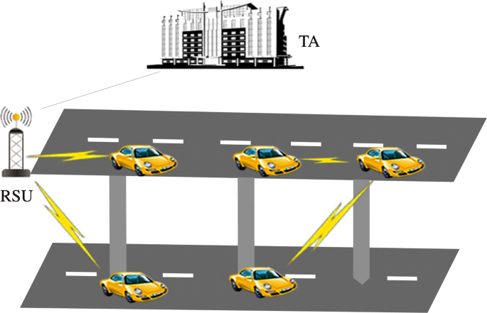
System architecture
-
RSUs are placed along the road, and have embedded processing and communication modules.
-
Vehicles may drive on an elevated road or on the road below the elevated road. Vehicles also have embedded processing and communication modules, which allow a vehicle to communicate with other nearby vehicle(s) or RSU for cooperative 3D positioning.

2.2 Design goals
Our goal is to design secure and privacy-preserving 3D vehicle positioning schemes for VANET. In our schemes, the vehicle is also referred to as a requester if it requests for some CP service. The CP service provider (a vehicle or an RSU) is known as the responder.
-
Authentication: To guarantee the security of the communications in our schemes, a requester and a responder have to be authenticated by each other. Furthermore, we need to ensure that messages received by the requester/responder have not been modified during the transmission. Finally, a new attack called backdoored pseudorandom generators is exposed [39] recently. If an entity’s chosen random number generator is backdoored, then an attacker may violate the security of a scheme. We require that if a backdoored pseudorandom generator is selected, then the authentication property still holds.
-
Vehicle privacy: In a 3D vehicle positioning scheme, entities other than the requester and the responder should not learn the real identities and positions of the participating vehicles.
-
Low error rate: A requester may determine its 3D position with overwhelming success rate and within a reasonable time frame (i.e. short delay).
2.3 Distance Function
In our schemes, we have to calculate the distance between two entities. We first consider the 2D condition. Suppose the position coordinates of the two entities are L1=(x1,y1) and L2=(x2,y2), where xi and yi are the longitude and latitude of a entity’s position, i∈{1,2}. Generally, a positioning system has some errors. Here, we assume the 2D positioning accuracy of each entity is ε.
As previously discussed, our first scheme is designed for V2R communications. We assume the RSU’s position coordinates are error-free. Then, we have the distance function
The second is designed for V2V communications, and we assume that there may exist errors in the coordinates of the two vehicles. We have the distance function
2.4 Nonce generator and hedged extractor
The nonce generator (NG) and hedged extractor (HE) are used to generate the randomness required to mitigate backdoored pseudorandom generators.
The algorithm NG takes as input the security parameter 1k, a current state St, and a nonce selector ω, and returns a nonce n0 belonging to the range set {0,1}∗ of NG as well as an updated state St′ through NG(1k,ω,St)→(n0,St′). HE takes a seed xk∈{0,1}∗, a message m, and a nonce n0 to deterministically return a string r=HE(xk,(m,n0)) [40].
3 Proposed secure and privacy-preserving 3D vehicle positioning for V2R communications
In this section, we present our first proposed scheme, which requires that a vehicle that intends to run a CP protocol to connect to an RSU directly. We also assume that a vehicle may learn its 2D coordinates, the 2D positioning accuracy is Δ m, and the height of elevated road is h m.
The scheme consists of four stages, namely setup, registration, secure channel establishment, and secure location proof. In the first stage, the TA generates the system parameters and master key. The vehicles and RSUs are enrolled by the TA in the second stage. In the third stage, a secure channel is established between a vehicle and an RSU. The secure channel is used to protect the privacy of the vehicle. In the fourth stage, the vehicle and the RSU run a V2R CP protocol for secure positioning.
3.1 Setup
On input a security parameter λ, TA performs the following:
-
1.
Selects a cyclic multiplicative group \(\mathbb {G}\) with prime order q and chooses a generator \(g\in \mathbb {G}\).
-
2.
Generates a master key s and the corresponding master public key g0. The master key will be used by the TA to issue certificates for the vehicles and RSUs in the system. The master public key will be used to verify the validity of the certificates.
-
3.
Chooses a symmetric encryption scheme \(\mathcal {E}_{K_{1}}(\cdot)/\mathcal {D}_{K_{1}}(\cdot)\), and a MAC scheme \(\mathcal {M}_{K_{2}}\). For simplicity, we assume the symmetric key K1 used in the symmetric encryption scheme and the symmetric key K2 used in the MAC scheme have the same length.
-
4.
Chooses a hash function H:{0,1}∗→{0,1}l, where l is the bit-length of the symmetric key used in \(\mathcal {E}_{K}(\cdot)/\mathcal {D}_{K}(\cdot)\) and \(\mathcal {M}_{K}\).
-
5.
Publishes \(\text {pub}=\left (\mathbb {G}, q, H, g_{0}, g, \mathcal {E}_{K_{1}}(\cdot)/\mathcal {D}_{K_{1}}(\cdot), \mathcal {M}_{K_{2}}\right)\) as the system parameters.
3.2 Registration
The vehicles and RSUs have to be enrolled by the TA.
For an RSU \(\mathcal {R}_{j}\), it runs the nonce generator NG to generate a nonce nj and a next state \(St^{\prime }_{j}\) through \(\phantom {\dot {i}\!}\left (n_{j}, St^{\prime }_{j}\right)\leftarrow \text {NG}\left (\mu _{j}, {St}_{j}\right)\) with a current state Stj and a nonce selector μj and then generates a randomness rsj used in the next step with hedged extractor HE through rsj←HE(xkj,(mj,nj)). Then, it computes \( {rp}_{j}=g^{{rs}_{j}}\), (rpj,rsj) to be used as the public/private key pair of \(\mathcal {R}_{j}\). TA also issues a certificate \(\text {cert}_{\mathcal {R}_{j}}\) for \(\mathcal {R}_{j}\). In our paper, we assume that \(\mathcal {R}_{j}\)’s position information
is included in \(\text {cert}_{\mathcal {R}_{i}}\), where \(x_{\mathcal {R}_{j}}\) and \(y_{\mathcal {R}_{j}}\) are longitude and latitude of \(\mathcal {R}_{j}\)’s position, \(z_{\mathcal {R}_{j}}\) is the height of \(\mathcal {R}_{j}\) from the ground, and \(z_{\mathcal {R}_{j}}>h\). Since the location of the \(\mathcal {R}_{j}\) is fixed, \(L_{\mathcal {R}_{j}}\) is a fixed and known coordinate.
For vehicle \(\mathcal {V}_{i}\), it runs the nonce generator NG to generate a nonce ni and a next state \(St^{\prime }_{i}\) through \(\phantom {\dot {i}\!}\left (n_{i}, St^{\prime }_{i}\right)\leftarrow \text {NG}(\mu _{i}, {St}_{i})\) with a current state Sti and a nonce selector μi and generates a randomness vsi used in the next step with hedged extractor HE though vsi←HE(xki,(mi,ni)). Then, it computes \( {vp}_{i}=g^{{vs}_{i}}\), (vpi,vsi) to be used as the public/private key pair of \(\mathcal {V}_{i}\). TA also issues an anonymous certificate \(\text {cert}_{\mathcal {V}_{i}}\) for \(\mathcal {V}_{i}\). To further enhance the privacy of a vehicle, the vehicle may ask TA to issue a pool of anonymous certificates for itself. Each anonymous certificate is only for short-term usage.
3.3 Secure channel establishment
We assume an RSU will periodically broadcast its certificates in its communication range and the altitude of the RSU is higher than that of the elevated road. Assume a vehicle \(\mathcal {V}_{i}\) wants to run a CP protocol to learn its 3D position and it may connect to the RSU \(\mathcal {R}_{j}\) directly. In this stage, a secure channel between Rj and Vi is established.
When \(\mathcal {V}_{i}\) enters the communication range of \(\mathcal {R}_{j}\), it first verifies the validity of \(\text {cert}_{\mathcal {R}_{j}}\). If the certificate is valid, then \(\mathcal {V}_{i}\) runs the nonce generator NG to generate a nonce n1 and a next state \(St^{\prime }_{1}\) through \(\left (n_{1}, St^{\prime }_{1}\right)\leftarrow \text {NG}\left (\mu _{1}, {St}_{1}\right)\) with a current state St1 and a nonce selector μ1. Then, it generates a randomness r used in the next step with hedged extractor HE though r←HE(xk1,(m1,n1)), computes u=gr, and sends \(\left (\text {cert}_{\mathcal {V}_{i}}, u\right)\) to \(\mathcal {R}_{j}\). \(\mathcal {V}_{i}\) computes
We note that, from \(\text {cert}_{\mathcal {R}_{j}}\), \(\mathcal {V}_{i}\) may learn the position information of Rj.
On receiving \(\left (\text {cert}_{\mathcal {V}_{i}}, u\right)\), \(\mathcal {R}_{j}\) computes
The session key used to establish a secure channel is \(sk=k_{\mathcal {V}_{i}, \mathcal {R}_{j}}=k_{\mathcal {R}_{j}, \mathcal {V}_{i}}\).
3.4 Secure location proof
Once the session key is established, \(\mathcal {V}_{i}\) and \(\mathcal {R}_{j}\) may run our V2R CP protocol—see Fig. 2. In the first two phases of our protocol, \(\mathcal {V}_{i}\) and \(\mathcal {R}_{j}\) repeat the following three steps in a period of time Δt. We will show how to choose Δt in our simulation.

Proposed V2R CP protocol
Step 1: Let η be the session round. \(\mathcal {R}_{j}\) performs the following:
-
1.
Sends its current timestamp \({ts}_{\mathcal {R}_{j} \eta }\) to \(\mathcal {V}_{i}\), where η is initially set to 1.
-
2.
Generates a MAC \(\text {MAC}_{\mathcal {R}_{j} \eta }=\mathcal {M}_{sk}\left ({ts}_{\mathcal {R}_{j} \eta },\eta \right)\) and sends \(\text {MAC}_{\mathcal {R}_{j} \eta }\) to \(\mathcal {V}_{i}\).
Step 2: We assume that \(\mathcal {V}_{i}\) receives \({ts}_{\mathcal {R}_{j} \eta }\) at time \({ts}_{\mathcal {V}_{i} \eta }\) and its location information is
at this time. \(\mathcal {V}_{i}\) performs the following:
-
1.
Sends \({ts}_{\mathcal {V}_{i}\eta }\) to \(\mathcal {R}_{j}\).
-
2.
On receiving \(\text {MAC}_{\mathcal {R}_{j\eta }}\), checks \(\text {MAC}_{\mathcal {R}_{j\eta }}\stackrel {?}{=}\mathcal {M}_{sk}\left ({ts}_{\mathcal {R}_{j\eta }},\eta \right)\). If the equation holds, then proceeds to the next sub-step; otherwise, aborts.
-
3.
Generates a ciphertext \(C_{\mathcal {V}_{i} \eta }=\mathcal {E}_{sk} \left (L_{\mathcal {V}_{i}\eta }\right)\) and a MAC \(\text {MAC}_{\mathcal {V}_{i} \eta }=\mathcal {M}_{sk}\left (C_{\mathcal {V}_{i} \eta },{ts}_{\mathcal {V}_{i}\eta },\eta \right)\).
-
4.
Sends \(\left (C_{\mathcal {V}_{i} \eta }, \text {MAC}_{\mathcal {V}_{i} \eta }\right)\) to \(\mathcal {R}_{j}\).
Step 3: We assume that \(\mathcal {R}_{j}\) receives \({ts}_{\mathcal {V}_{i}\eta }\) at time \({ts}_{\mathcal {R}_{j}\eta +1}\). It performs the following:
-
1.
On receiving \(\left (C_{\mathcal {V}_{i} \eta }, \text {MAC}_{\mathcal {V}_{i} \eta }\right)\), verifies the validity of \(\text {MAC}_{\mathcal {V}_{i} \eta }\) by checking \(\text {MAC}_{\mathcal {V}_{i} \eta }\stackrel {?}{=}\mathcal {M}_{sk}(C_{\mathcal {V}_{i} \eta },{ts}_{\mathcal {V}_{i}\eta }, \eta)\). If the equation holds, then computes \(L_{\mathcal {V}_{i}\eta }=\mathcal {D}_{sk} (C_{\mathcal {V}_{i} \eta });\) otherwise, aborts.
-
2.
Sets η=η+1 and proceeds to step 1.
Once phase 1 has successfully concluded, \(\mathcal {V}_{i}\) may calculate its 3D position information in phase 2. We note that, for round n, steps 2 and 3 are used to acknowledge that \(\mathcal {V}_{i}\) has received the messages broadcasted by \(\mathcal {R}_{j}\) in step 1. Assume the final session round is n and 2D positioning accuracy is Δ m.
\(\mathcal {V}_{i}\) performs the following:
-
1.
Calculates the theoretical distance range \([{ls}_{\text {min}, \mathcal {V}_{i}\eta }, {ls}_{\text {max}, \mathcal {V}_{i} \eta }]\) in the case \(\mathcal {V}_{i}\) is on the elevated road, where
$$\begin{array}{@{}rcl@{}} {ls}_{\text{min}, \mathcal{V}_{i} \eta}=\sqrt{Df\left(L_{\mathcal{V}_{i}\eta}, L_{\mathcal{R}_{j}}, -\Delta\right)^{2}+\left(z_{\mathcal{R}_{j}}-h\right)^{2}} \end{array} $$(5)$$\begin{array}{@{}rcl@{}} {ls}_{\text{max}, \mathcal{V}_{i} \eta}=\sqrt{Df\left(L_{\mathcal{V}_{i}\eta}, L_{\mathcal{R}_{j}}, +\Delta\right)^{2}+\left(z_{\mathcal{R}_{j}}-h\right)^{2}} \end{array} $$(6)Computes the accumulated theoretical distance range
$$\begin{array}{@{}rcl@{}}\left[{Ls}_{\text{min}, \mathcal{V}_{i}},{Ls}_{\text{max}, \mathcal{V}_{i}}\right]=\left[\sum\limits_{\eta=1}^{n-1}{{ls}_{\text{min}, \mathcal{V}_{i} \eta}},\sum\limits_{\eta=1}^{n-1}{{ls}_{\text{max}, \mathcal{V}_{i} \eta}}\right] \end{array} $$(7) -
2.
Calculates the theoretical distance range \([{ld}_{\text {min}, \mathcal {V}_{i} \eta }, {ld}_{\text {max}, \mathcal {V}_{i} \eta }]\) in the case \(\mathcal {V}_{i}\) is under the elevated road, where
$$\begin{array}{@{}rcl@{}}{ld}_{\text{min}, \mathcal{V}_{i} \eta}=\sqrt{Df \left(L_{\mathcal{V}_{i} \eta}, L_{\mathcal{R}_{j}}, -\Delta\right)^{2}+ z_{\mathcal{R}_{j}}^{2}} \end{array} $$(8)$$\begin{array}{@{}rcl@{}}{ld}_{\text{max}, \mathcal{V}_{i} \eta}=\sqrt{Df\left(L_{\mathcal{V}_{i} \eta}, L_{\mathcal{R}_{j}}, +\Delta\right)^{2}+ z_{\mathcal{R}_{j}}^{2}} \end{array} $$(9)Computes the accumulated theoretical distance range
$$\begin{array}{@{}rcl@{}} \left[{Ld}_{\text{min}, \mathcal{V}_{i}},{Ld}_{\text{max}, \mathcal{V}_{i}}\right]=\left[\sum\limits_{\eta=1}^{n-1}{{ld}_{\text{min}, \mathcal{V}_{i} \eta}},\sum\limits_{\eta=1}^{n-1}{{ld}_{\text{max}, \mathcal{V}_{i} \eta}}\right] \end{array} $$(10) -
3.
Calculates the computational distance \(s_{\mathcal {V}_{i} \eta }\) between \(\mathcal {V}_{i}\) and \(\mathcal {R}_{j}\), where
$$\begin{array}{@{}rcl@{}}s_{\mathcal{V}_{i} \eta}=C \times \left[\left({ts}_{\mathcal{V}_{i} \eta+1}-{ts}_{\mathcal{V}_{i} \eta}\right)/2\right] \end{array} $$(11)Computes the accumulated computational distance
$$\begin{array}{@{}rcl@{}}S_{\mathcal{V}_{i}}=\sum\limits_{\eta=1}^{n-1}{s_{\mathcal{V}_{i} \eta}} \end{array} $$(12) -
4.
By using \(S_{\mathcal {V}_{i}}\), \(\left [{Ls}_{\text {min}, \mathcal {V}_{i}},{Ls}_{\text {max}, \mathcal {V}_{i}}\right ]\) and \(\left [{Ld}_{\text {min}, \mathcal {V}_{i}},{Ld}_{\text {max}, \mathcal {V}_{i}}\right ]\), we can calculate \({Po}_{\mathcal {V}_{i}}\) and \({Pu}_{\mathcal {V}_{i}}\), where \({Po}_{\mathcal {V}_{i}}\) is the probability that \(\mathcal {V}_{i}\) is on the elevated road and \({Pu}_{\mathcal {V}_{i}}\) is the probability that \(\mathcal {V}_{i}\) is not on the elevated road.
There are two cases where we calculate the probability.
-
(a)
The first is that there is no overlap between \(\left [{Ls}_{\text {min}, \mathcal {V}_{i}},{Ls}_{\text {max}, \mathcal {V}_{i}}\right ]\) and \(\left [{Ld}_{\text {min}, \mathcal {V}_{i}},{Ld}_{\text {max}, \mathcal {V}_{i}}\right ]\). If \(S_{\mathcal {V}_{i}}\) is in the range of \(\left [{Ls}_{\text {min}, \mathcal {V}_{i}},{Ls}_{\text {max}, \mathcal {V}_{i}}\right ]\) or on the left side of \(\left [{Ls}_{\text {min}, \mathcal {V}_{i}},{Ls}_{\text {max}, \mathcal {V}_{i}}\right ]\), then \({Po}_{\mathcal {V}_{i}}=1\); if \(S_{\mathcal {V}_{i}}\) is in the range of \(\left [{Ld}_{\text {min}, \mathcal {V}_{i}},{Ld}_{\text {max}, \mathcal {V}_{i}}\right ]\) or on the right side of \(\left [{Ld}_{\text {min}, \mathcal {V}_{i}},{Ld}_{\text {max}, \mathcal {V}_{i}}\right ]\), then \({Pu}_{\mathcal {V}_{i}}=1\). If \(S_{\mathcal {V}_{i}}\) is not within the overlap between the \(\left [{Ls}_{\text {min}, \mathcal {V}_{i}},{Ls}_{\text {max}, \mathcal {V}_{i}}\right ]\) and \(\left [{Ld}_{\text {min}, \mathcal {V}_{i}},{Ld}_{\text {max}, \mathcal {V}_{i}}\right ]\), then we will take the principle of proximity to calculate the probability.
-
(b)
The second is that there is overlap between \(\left [{Ls}_{\text {min}, \mathcal {V}_{i}},{Ls}_{\text {max}, \mathcal {V}_{i}}\right ]\) and \(\left [{Ld}_{\text {min}, \mathcal {V}_{i}},{Ld}_{\text {max}, \mathcal {V}_{i}}\right ]\). If the \(S_{\mathcal {V}_{i}}\) is in the range of \(\left [{Ls}_{\text {min}, \mathcal {V}_{i}},{Ls}_{\text {max}, \mathcal {V}_{i}}\right ]\) but not in the overlapping range or on the left side of \(\left [{Ls}_{\text {min}, \mathcal {V}_{i}},{Ls}_{\text {max}, \mathcal {V}_{i}}\right ]\), then \({Po}_{\mathcal {V}_{i}}=1\); if the \(S_{\mathcal {V}_{i}}\) in the \(\left [{Ld}_{\text {min}, \mathcal {V}_{i}},{Ld}_{\text {max}, \mathcal {V}_{i}}\right ]\) but not in the overlapping range or the right side of the \(\left [{Ld}_{\text {min}, \mathcal {V}_{i}},{Ld}_{\text {max}, \mathcal {V}_{i}}\right ]\), then \({Pu}_{\mathcal {V}_{i}}=1\); if the \(S_{\mathcal {V}_{i}}\) is in the range of overlap, then using the same principle of proximity to calculate the probability.
The concrete calculation is as follows:
1. If \({Ls}_{\text {max}, \mathcal {V}_{i}}\leq {Ld}_{\text {min}, \mathcal {V}_{i}}\)
-
(a)
If \(S_{\mathcal {V}_{i}}\leq {Ls}_{\text {max}, \mathcal {V}_{i}}\), \({Po}_{\mathcal {V}_{i}}=1\), \({Pu}_{\mathcal {V}_{i}}=0\).
-
(b)
If \(S_{\mathcal {V}_{i}}\geq {Ld}_{\text {min}, \mathcal {V}_{i}}\), \({Po}_{\mathcal {V}_{i}}=0\), \({Pu}_{\mathcal {V}_{i}}=1\).
-
(c)
If \(S_{\mathcal {V}_{i}}>{Ls}_{\text {max}, \mathcal {V}_{i}}\) and \(S_{\mathcal {V}_{i}}<{Ld}_{\text {min}, \mathcal {V}_{i}}\), \({Po}_{\mathcal {V}_{i}}=\frac {{Ld}_{\text {min}, \mathcal {V}_{i}}-S_{\mathcal {V}_{i}}}{{Ld}_{\text {min}, \mathcal {V}_{i}}-{Ls}_{\text {max}, \mathcal {V}_{i}}}\), \({Pu}_{\mathcal {V}_{i}}=\frac {S_{\mathcal {V}_{i}}-{Ls}_{\text {max}, \mathcal {V}_{i}}}{{Ld}_{\text {min}, \mathcal {V}_{i}}-{Ls}_{\text {max}, \mathcal {V}_{i}}}\).
2. If \({Ls}_{\text {min}, \mathcal {V}_{i}}<{Ld}_{\text {min}, \mathcal {V}_{i}}<{Ls}_{\text {max}, \mathcal {V}_{i}}<{Ld}_{\text {max}, \mathcal {V}_{i}}\)
-
(a)
If \(S_{\mathcal {V}_{i}}\leq {Ld}_{\text {min}, \mathcal {V}_{i}}\), \({Po}_{\mathcal {V}_{i}}=1\), \({Pu}_{\mathcal {V}_{i}}=0\).
-
(b)
If \(S_{\mathcal {V}_{i}}\geq {Ls}_{\text {max}, \mathcal {V}_{i}}\), \({Po}_{\mathcal {V}_{i}}=0\), \({Pu}_{\mathcal {V}_{i}}=1\).
-
(c)
If \(S_{\mathcal {V}_{i}}>{Ld}_{\text {min}, \mathcal {V}_{i}}\) and \(S_{\mathcal {V}_{i}}<{Ls}_{\text {max}, \mathcal {V}_{i}}\), \({Po}_{\mathcal {V}_{i}}=\frac {{Ls}_{\text {max}, \mathcal {V}_{i}}-S_{\mathcal {V}_{i}}}{{Ls}_{\text {max}, \mathcal {V}_{i}}-{Ld}_{\text {min}, \mathcal {V}_{i}}}\), \({Pu}_{\mathcal {V}_{i}}=\frac {S_{\mathcal {V}_{i}}-{Ld}_{\text {min}, \mathcal {V}_{i}}}{{Ls}_{\text {max}, \mathcal {V}_{i}}-{Ld}_{\text {min}, \mathcal {V}_{i}}}\).
3. If \({Po}_{\mathcal {V}_{i}}> {Pu}_{\mathcal {V}_{i}}\), then it can be determined that \(\mathcal {V}_{i}\) is on the elevated road. If \({Po}_{\mathcal {V}_{i}}< {Pu}_{\mathcal {V}_{i}}\), then it can be determined that \(\mathcal {V}_{i}\) is not on the elevated road. Therefore, the height of \(\mathcal {V}_{i}\) can be determined.
-
(a)
3.5 Security analysis
In the secure channel establishment stage, a secure channel is established between \(\mathcal {V}_{i}\) and \(\mathcal {R}_{j}\). Essentially, it is an anonymous one-pass authenticated key agreement protocol. A one-pass authenticated key agreement protocol requires only one entity to send a message to another entity. The secure channel can be established with a short delay. The one-pass authenticated key agreement protocol used in this paper is derived from the protocol in [37], which has been proven to be secure. Furthermore, in the one-pass authenticated key agreement protocol, the anonymous certificate is used to hide \(\mathcal {V}_{i}\)’s identity, and the position information of \(\mathcal {V}_{i}\) is sent through the secure channel. In addition, in the key agreement protocol, we use a nonce generator NG and a hedged extractor HE to generate the randomness. Thus, as shown in [40], this anonymous one-pass authenticated key agreement protocol is secured against backdoored pseudorandom generators. Therefore, the authentication and vehicle privacy properties are guaranteed.
4 Proposed secure and privacy-preserving 3D vehicle positioning for V2V communications
In the scheme introduced in the preceding section, the vehicles achieve 3D positioning via RSUs. However, RSUs have limited deployment and coverage. Therefore, we propose a 3D vehicle positioning scheme for V2V communications in this section.
The scheme also consists of four stages, namely setup, registration, secure channel establishment, and secure location proof. In the first stage, TA generates the system parameters and master key. The vehicles are enrolled by the TA in the second stage. In the third stage, a secure channel is established between a vehicle with a known 3D position and a vehicle with an unknown 3D position. The secure channel is used to protect the privacy of the two vehicles. In the last stage, the two vehicles run a V2V CP protocol for secure positioning. We assume that the vehicle with unknown 3D location can only obtain the exact 2D coordinates, and the height of elevated road is h m.
The setup and registration stages are the same as those in the previous scheme. Thus, in the following, we only introduce secure channel establishment and secure location proof stages.
4.1 Secure channel establishment
Assume a vehicle \(\mathcal {V}_{i}\) wishes to execute a V2V CP protocol to learn its 3D position, and it may connect to a vehicle \(\mathcal {V}_{j}\) with a known 3D position directly. At this stage, a secure channel between \(\mathcal {V}_{j}\) and \(\mathcal {V}_{i}\) is established.
When \(\mathcal {V}_{i}\) enters the communication range of \(\mathcal {V}_{j}\), it first verifies the validity of \(\text {cert}_{\mathcal {V}_{j}}\). If the certificate is valid, then \(\mathcal {V}_{i}\) runs the nonce generator NG to generate a nonce n1 and a next state \(St^{\prime }_{1}\) through (n1,St1′)←NG(μ1,St1) with a current state St1 and a nonce selector μ1, prior to generating a randomness r used in the next step with hedged extractor HE through r←HE(xk1,(m1,n1)). Then, it computes u=gr and sends \(({cert}_{\mathcal {V}_{i}}, u)\) to \(\mathcal {V}_{j}\). \(\mathcal {V}_{i}\) computes
On receiving \((\text {cert}_{\mathcal {V}_{i}}, u)\), \(\mathcal {R}_{j}\) computes
The session key used to establish a secure channel is \(sk=k_{\mathcal {V}_{i}, \mathcal {V}_{j}}=k_{\mathcal {V}_{j}, \mathcal {V}_{i}}\).
4.2 Location proof
After the session key is established, \(\mathcal {V}_{i}\) and \(\mathcal {V}_{j}\) may run our V2V CP protocol—see Fig. 3. The protocol has two phases. In the first phase, \(\mathcal {V}_{i}\) and \(\mathcal {V}_{j}\) repeat the following three steps in time period Δt. We will show how to choose Δt in our simulation.

Proposed V2V CP protocol
Step 1: Let ζ be the session round, and ζ is initially set to 1. \(\mathcal {V}_{j}\) obtains its location
at time \({ts}_{\mathcal {V}_{j} \zeta }\). \(\mathcal {V}_{j}\) performs the following:
-
1.
Sends \({ts}_{\mathcal {V}_{j} \zeta }\) to \(\mathcal {V}_{i}\).
-
2.
Generates a ciphertext \(C_{\mathcal {V}_{j} \zeta }=\mathcal {E}_{sk} \left (L_{\mathcal {V}_{j} \zeta }\right)\) and a MAC \(\text {MAC}_{\mathcal {V}_{j} \zeta }=\mathcal {M}_{sk}\left (C_{\mathcal {V}_{j} \zeta },{ts}_{\mathcal {V}_{j} \zeta }, \zeta \right)\).
-
3.
Sends \(\left (C_{\mathcal {V}_{j} \zeta }, \text {MAC}_{\mathcal {V}_{j} \zeta }\right)\) to \(\mathcal {V}_{i}\).
Step 2: Assume that \(\mathcal {V}_{i}\) receives \({ts}_{\mathcal {V}_{j} \zeta }\) at time \({ts}_{\mathcal {V}_{i} \zeta }\) and its location information is
at this time. \(\mathcal {V}_{i}\) performs the following:
-
1.
Sends \({ts}_{\mathcal {V}_{i} \zeta }\) to \(\mathcal {V}_{j}\).
-
2.
On receiving \(\text {MAC}_{\mathcal {V}_{j \zeta }}\), checks \(\text {MAC}_{\mathcal {V}_{j} \zeta }\stackrel {?}{=}\mathcal {M}_{sk}\left (C_{\mathcal {V}_{j} \zeta },{ts}_{\mathcal {V}_{j} \zeta }, \zeta \right)\). If the equation holds, then computes \(L_{\mathcal {V}_{j} \zeta }=\mathcal {D}_{sk} \left (C_{\mathcal {V}_{j} \zeta }\right)\) and proceeds to the next sub-step; otherwise, aborts.
-
3.
Generates a ciphertext \(C_{\mathcal {V}_{i} \zeta }=\mathcal {E}_{sk} \left (L_{\mathcal {V}_{i} \zeta }\right)\) and a MAC \(\text {MAC}_{\mathcal {V}_{i} \zeta }=\mathcal {M}_{sk}\left (C_{\mathcal {V}_{i} \zeta },{ts}_{\mathcal {V}_{i} \zeta }, \zeta \right)\).
-
4.
Sends \(\left (C_{\mathcal {V}_{i} \zeta }, \text {MAC}_{\mathcal {V}_{i} \zeta }\right)\) to \(\mathcal {V}_{j}\).
Step 3: Assume that \(\mathcal {V}_{j}\) receives \({ts}_{\mathcal {V}_{i} \zeta }\) at time \({ts}_{\mathcal {V}_{j} \zeta +1}\). It performs the following:
-
1.
On receiving \(\left (C_{\mathcal {V}_{i} \zeta }, \text {MAC}_{\mathcal {V}_{i} \zeta }\right)\), verifies the validity of \(\text {MAC}_{\mathcal {V}_{i} \zeta }\) by checking \(\text {MAC}_{\mathcal {V}_{i} \zeta }\stackrel {?}{=}\mathcal {M}_{sk}\left (C_{\mathcal {V}_{i} \zeta },{ts}_{\mathcal {V}_{i} \zeta }, \zeta \right)\). If the equation holds, then computes \(L_{\mathcal {V}_{i} \zeta }=\mathcal {D}_{sk} \left (C_{\mathcal {V}_{i} \zeta }\right);\) otherwise, aborts.
-
2.
Sets ζ=ζ+1 and proceeds to step 1.
Once phase 1 is successfully finished, \(\mathcal {V}_{i}\) may calculate its 3D position information in phase 2. Assume the final session round is n and 2D positioning accuracy is Δ m.
\(\mathcal {V}_{i}\) performs the following.
-
1.
Calculates the theoretical distance range \(\left [{ls}_{\text {min}, \mathcal {V}_{i} \zeta }, {ls}_{\text {max}, \mathcal {V}_{i} \zeta }\right ]\) in the case \(\mathcal {V}_{i}\) and \(\mathcal {V}_{j}\) are at the same layer, where
$$\begin{array}{@{}rcl@{}} {ls}_{\text{min}, \mathcal{V}_{i} \zeta}=Df^{\prime}\left(L_{\mathcal{V}_{i}, {ts}_{\mathcal{V}_{i} \zeta}}, L_{\mathcal{V}_{j}, {ts}_{\mathcal{V}_{j} \zeta}}, -2\Delta\right) \end{array} $$(15)$$\begin{array}{@{}rcl@{}}{ls}_{\text{max}, \mathcal{V}_{i}, \zeta}=Df^{\prime}\left(L_{\mathcal{V}_{i}, {ts}_{\mathcal{V}_{i} \zeta}}, L_{\mathcal{V}_{j}, {ts}_{\mathcal{V}_{j} \zeta}}, +2\Delta\right) \end{array} $$(16)Computes the accumulated theoretical distance range
$$\begin{array}{@{}rcl@{}} [{Ls}_{\text{min}, \mathcal{V}_{i}},{Ls}_{\text{max}, \mathcal{V}_{i}}]=\left[\sum\limits_{\zeta=1}^{n-1}{{ls}_{\text{min}, \mathcal{V}_{i} \zeta}},\sum\limits_{\zeta=1}^{n-1}{{ls}_{\text{max}, \mathcal{V}_{i} \zeta}}\right] \end{array} $$(17) -
2.
Calculates the theoretical distance range \(\left [{ld}_{\text {min}, \mathcal {V}_{i} \zeta }, {ld}_{\text {max}, \mathcal {V}_{i} \zeta }\right ]\) in the case \(\mathcal {V}_{i}\) and \(\mathcal {V}_{j}\) are at different layers, where
$$\begin{array}{@{}rcl@{}} {ld}_{\text{min}, \mathcal{V}_{i} \zeta}=\sqrt{{ls}_{\text{min}, \mathcal{V}_{i} \zeta}^{2}+h^{2}} \end{array} $$(18)$$\begin{array}{@{}rcl@{}} {ld}_{\text{max}, \mathcal{V}_{i} \zeta}=\sqrt{{ls}_{\text{max}, \mathcal{V}_{i} \zeta}^{2}+h^{2}} \end{array} $$(19)Computes the accumulated theoretical distance range
$$\begin{array}{@{}rcl@{}} \left[{Ld}_{\text{min}, \mathcal{V}_{i}},{Ld}_{\text{max}, \mathcal{V}_{i}}\right]\,=\,\left[\sum\limits_{\zeta=1}^{n-1}{{ld}_{\text{min}, \mathcal{V}_{i} \zeta}},\sum\limits_{\zeta=1}^{n-1}{{ld}_{\text{max}, \mathcal{V}_{i} \zeta}}\right] \end{array} $$(20) -
3.
Calculates the computational distance \(s_{\mathcal {V}_{i} \zeta }\) between \(\mathcal {V}_{i}\) and \(\mathcal {V}_{j}\), where
$$\begin{array}{@{}rcl@{}} s_{\mathcal{V}_{i} \zeta}=C\times\left[\left({ts}_{\mathcal{V}_{i} \zeta+1}-{ts}_{\mathcal{V}_{i} \zeta}\right)/2\right] \end{array} $$(21)Computes the accumulated computational distance
$$\begin{array}{@{}rcl@{}} S_{\mathcal{V}_{i}}=\sum\limits_{\zeta=1}^{n-1}{s_{\mathcal{V}_{i} \zeta}} \end{array} $$(22) -
4.
By using \(S_{\mathcal {V}_{i}}\), \(\left [{Ls}_{\text {min}, \mathcal {V}_{i}},{Ls}_{\text {max}, \mathcal {V}_{i}}\right ]\) and \(\left [{Ld}_{\text {min}, \mathcal {V}_{i}},{Ld}_{max, \mathcal {V}_{i}}\right ]\), we can calculate \({Po}_{\mathcal {V}_{i}}\) and \({Pu}_{\mathcal {V}_{i}}\), where \({Po}_{\mathcal {V}_{i}}\) is the probability that \(\mathcal {V}_{i}\) is on the elevated road and \({Pu}_{\mathcal {V}_{i}}\) is the probability that \(\mathcal {V}_{i}\) is not on the elevated road. The calculation is as follows:
1. If \({Ls}_{\text {max}, \mathcal {V}_{i}}\leq {Ld}_{\text {min}, \mathcal {V}_{i}}\)
-
(a)
If \(S_{\mathcal {V}_{i}}\leq {Ls}_{\text {max}, \mathcal {V}_{i}}\), \({Po}_{\mathcal {V}_{i}}=1\), \({Pu}_{\mathcal {V}_{i}}=0\).
-
(b)
If \(S_{\mathcal {V}_{i}}\geq {Ld}_{\text {min}, \mathcal {V}_{i}}\), \({Po}_{\mathcal {V}_{i}}=0\), \({Pu}_{\mathcal {V}_{i}}=1\).
-
(c)
If \(S_{\mathcal {V}_{i}}>{Ls}_{\text {max}, \mathcal {V}_{i}}\) and \(S_{\mathcal {V}_{i}}<{Ld}_{\text {min}, \mathcal {V}_{i}}\), \({Po}_{\mathcal {V}_{i}}=\frac {{Ld}_{\text {min}, \mathcal {V}_{i}}-S_{\mathcal {V}_{i}}}{{Ld}_{\text {min}, \mathcal {V}_{i}}-{Ls}_{\text {max}, \mathcal {V}_{i}}}\), \({Pu}_{\mathcal {V}_{i}}=\frac {S_{\mathcal {V}_{i}}-{Ls}_{\text {max}, \mathcal {V}_{i}}}{{Ld}_{\text {min}, \mathcal {V}_{i}}-{Ls}_{\text {max}, \mathcal {V}_{i}}}\).
2. If \({Ls}_{\text {min}, \mathcal {V}_{i}}<{Ld}_{\text {min}, \mathcal {V}_{i}}<{Ls}_{\text {max}, \mathcal {V}_{i}}<{Ld}_{\text {max}, \mathcal {V}_{i}}\)
-
(a)
If \(S_{\mathcal {V}_{i}}\leq {Ld}_{\text {min}, \mathcal {V}_{i}}\), \({Po}_{\mathcal {V}_{i}}=1\), \({Pu}_{\mathcal {V}_{i}}=0\).
-
(b)
If \(S_{\mathcal {V}_{i}}\geq {Ls}_{\text {max}, \mathcal {V}_{i}}\), \({Po}_{\mathcal {V}_{i}}=0\), \({Pu}_{\mathcal {V}_{i}}=1\).
-
(c)
If \(S_{\mathcal {V}_{i}}>{Ld}_{\text {min}, \mathcal {V}_{i}}\) and \(S_{\mathcal {V}_{i}}<{Ls}_{\text {max}, \mathcal {V}_{i}}\), \({Po}_{\mathcal {V}_{i}}=\frac {{Ls}_{\text {max}, \mathcal {V}_{i}}-S_{\mathcal {V}_{i}}}{{Ls}_{\text {max}, \mathcal {V}_{i}}-{Ld}_{\text {min}, \mathcal {V}_{i}}}\), \({Pu}_{\mathcal {V}_{i}}=\frac {S_{\mathcal {V}_{i}}-{Ld}_{\text {min}, \mathcal {V}_{i}}}{{Ls}_{\text {max}, \mathcal {V}_{i}}-{Ld}_{\text {min}, \mathcal {V}_{i}}}\).
3. If \({Po}_{\mathcal {V}_{i}}> {Pu}_{\mathcal {V}_{i}}\), it can be determined that \(\mathcal {V}_{i}\) and \(\mathcal {V}_{j}\) are in the same layer. If \({Po}_{\mathcal {V}_{i}}< {Pu}_{\mathcal {V}_{i}}\), then it can be determined that \(\mathcal {V}_{i}\) and \(\mathcal {V}_{j}\) are in different layers. Therefore, the height of \(\mathcal {V}_{i}\) can be determined.
-
(a)
4.3 Security analysis
In the secure channel establishment stage, a secure channel is established between \(\mathcal {V}_{i}\) and \(\mathcal {V}_{j}\). Essentially, it is an anonymous one-pass authenticated key agreement protocol which is the same as that of the previous scheme. Furthermore, in the one-pass authenticated key agreement protocol, anonymous certificates are used to hide the identity of \(\mathcal {V}_{i}\) and \(\mathcal {V}_{j}\) and the position information of \(\mathcal {V}_{i}\) and \(\mathcal {V}_{j}\) is sent through the secure channel. In addition, in the key agreement protocol, we use a nonce generator NG and a hedged extractor HE to generate the randomness. Thus, this anonymous one-pass authenticated key agreement protocol is secured against backdoored pseudorandom generators. This also ensures the authentication and vehicle privacy properties.
5 Simulation
In this section, we evaluate the performance of our schemes using NS-2.35, which is an open source network communication simulator. In NS-2.35, there are three types of propagation models: free space, two-ray ground model, and shadowing model [38]. In the first two models, the distance is the only variable parameter in the simulation, but the introduction of random events in the shadowing model is closer to the real-world scenario. So in our experiment, we chose shadowing model as our experimental model.
The purpose of our scheme is to accurately determine the position of the vehicle, so we need to find an appropriate time segment Δt to ensure the correct rate of positioning. Our experiments were implemented on a Linux machine using an Intel Core i7-4790 at frequency of 3.60 GHz. In our experiments, the channel bandwidth bound was 6 Mbps. The vehicle’s speed ranged from 30 to 60 km/h, and the average speed was 50 km/h. The communication radius of an RSU and each vehicle was set to be 300 m. For each experiment, the simulation time was about 20 s. Therefore, we can think of the vehicle’s speed remaining constant during the simulations.
5.1 3D positioning based on V2R communications
Figure 4 shows the relationship between time segment Δt and correct rate P in the case of 3D positioning for V2R communications. We note that when Δt≥0.8 s, P>0.9, and when Δt≥1.4 s, P=1. In other words, when Δt≥1.4 s, the vehicle can determine its position accurately. So the vehicle needs to interact with the RSU for about 1.4 s before determining its location. It is also clear that 1.4 s is an acceptable delay.

Correct rate in the case of 3D positioning for V2R communications
5.2 3D positioning based on V2V communications
In this section, a vehicle that needs to be positioned achieves 3D position via a vehicle whose position is known. This case is more complex than the previous case. In the previous case, the RSU is fixed and only the vehicle is moving. However in this case, two vehicles are moving simultaneously. So we have to consider the traveling direction of the two vehicles: opposite direction, face-to-face, and same direction.
Figure 5 shows the relationship between time segment Δt and correct rate P for 3D positioning in V2V communications between two vehicles traveling in the opposite direction. We note that when Δt≥1.3 s, P=1. So in this case, the vehicle will be able to determine the position within 1.3 s.

Correct rate when two vehicles are traveling in the opposite direction
Figure 6 shows the relationship between time segment Δt and correct rate P for 3D positioning in V2V communications for two vehicles traveling face-to-face. We note that when Δt≥1.5 s, P=1.

Correct rate when two vehicles are traveling face-to-face
The relationship between time segment Δt and correct rate P for 3D positioning in V2V communications for two vehicles traveling in the same direction is shown in the Fig. 7. When two vehicles travel in the same direction, due to the speed factor, the distance between the two vehicles may appear to gradually approach or stay away from or remain unchanged. When t>1.6 s, P>0.9 in the case of two vehicles approaching. When t>1.1 s, P>0.9 in the case of two vehicles away. When t>1.4 s, P>0.9 in the case of two vehicles remain unchanged. Again, such delays are acceptable in a typical real-world scenario.

Correct rate when two vehicles are traveling in the same direction
6 Conclusion
As smart vehicles become more commonplace and smart cities being the norm, ensuring accurate 3D vehicle positioning schemes (and potentially 4D and beyond in the foreseeable future) while also ensuring the security and privacy of the data and the participating vehicles will be increasingly important.
In this paper, we proposed two secure and privacy-preserving 3D positioning schemes for V2R and V2V communications in a VANET. We demonstrated the utility of both schemes using simulations, in the sense that the schemes achieve their design goals (i.e., 3D positioning of the vehicles) within an acceptable time frame without compromising the security and privacy of the data and the participating vehicles.
Future research includes extending the proposed schemes to consider multiple vehicles and other types of vehicles such as unmanned aerial vehicles (also known as drones).
Notes
http://www.star-telegram.com/news/traffic/your-commute/article122735029.html, last accessed May 13, 2018.
https://www.mysanantonio.com/news/local/article/Bandera-Road-s-future-tree-lined-boulevard-12558886.php, last accessed May 13, 2018.
References
L. Zhang, Q. Wu, J. Domingo-Ferrer, B. Qin, C. Hu, Distributed aggregate privacy-preserving authentication in vanets. IEEE T. Intell. Transp. Syst.18(3), 516–526 (2017).
S. Latif, S. Mahfooz, N. Ahmad, B. Jan, H. Farman, M. Khan, K. Han, Industrial internet of things based efficient and reliable data dissemination solution for vehicular ad hoc networks. Wirel. Commun. Mob. Com.2018:, 1–16 (2018).
C. Wu, Y. Ji, F. Liu, S. Ohzahata, T. Kato, Toward practical and intelligent routing in vehicular ad hoc networks. IEEE T. Veh. Technol.64(12), 5503–5519 (2015).
L. Zhang, Q. Wu, A. Solanas, J. Domingo-Ferrer, A scalable robust authentication protocol for secure vehicular communications. IEEE T. Veh. Technol.59(4), 1606–1617 (2010).
K. Abboud, W. Zhuang, Stochastic modeling of single-hop cluster stability in vehicular ad hoc networks. IEEE T. Veh. Technol.65(1), 226–240 (2016).
L. Zhang, Q. Wu, B. Qin, J. Domingo-Ferrer, B. Liu, Practical secure and privacy-preserving scheme for value-added applications in VANETs. Comput. Commun.71:, 50–60 (2015).
L. Zhang, OTIBAAGKA: a new security tool for cryptographic mix-zone establishment in vehicular ad hoc networks. IEEE T. Inf. Foren. Sec.12(12), 2998–3010 (2017).
X. Wei, W. Chen, B. Chen, B. Chen, B. Chen, et al, B-spline wavelet on interval finite element method for static and vibration analysis of stiffened flexible thin plate. CMC-Comput. Mater. Con.52(1), 53–71 (2016).
C. Wu, E. Zapevalova, Y. Chen, F. Li, Time optimization of multiple knowledge transfers in the big data environment. CMC-Comput. Mater. Con.54(3), 269–285 (2018).
L. Zhang, X. Meng, K. -K. R. Choo, Y. Zhang, F. Dai, Privacy-preserving cloud establishment and data dissemination scheme for vehicular cloud. IEEE T. Depend. Secure. 1:, 1–1 (2018). https://doi.org/10.1109/TDSC.2018.2797190.
J. Liu, J. Li, L. Zhang, F. Dai, Y. Zhang, X. Meng, J. Shen, Secure intelligent traffic light control using fog computing. Future Gener. Comp. Sy.78:, 817–824 (2018).
Z. Xia, N. N. Xiong, A. V. Vasilakos, X. Sun, Epcbir: An efficient and privacy-preserving content-based image retrieval scheme in cloud computing. Inform. Sci.387:, 195–204 (2017).
Z. Xia, X. Ma, Z. Shen, X. Sun, N. N. Xiong, B. Jeon, Secure image LBP feature extraction in cloud-based smart campus. IEEE Access. 6:, 30392–30401 (2018).
L. Zhang, C. Hu, Q. Wu, J. Domingo-Ferrer, B. Qin, Privacy-preserving vehicular communication authentication with hierarchical aggregation and fast response. IEEE Trans. Comput.65(8), 2562–2574 (2016).
J. Cui, Y. Zhang, Z. Cai, A. Liu, Y. Li, Securing display path for security-sensitive applications on mobile devices. CMC Comput. Mater. Contin. 55:, 17–35 (2018).
H. Cheng, Z. Su, N. Xiong, Y. Xiao, Energy-efficient node scheduling algorithms for wireless sensor networks using Markov Random Field model. Inform. Sci.329:, 461–477 (2016).
H. Cheng, D. Feng, X. Shi, C. Chen, Data quality analysis and cleaning strategy for wireless sensor networks. EURASIP J. Wirel. Comm.2018(1), 61 (2018).
B. Lin, W. Guo, N. Xiong, G. Chen, A. V. Vasilakos, H. Zhang, A pretreatment workflow scheduling approach for big data applications in multicloud environments. IEEE Trans. Netw. Serv.13(3), 581–594 (2016).
H. Zheng, W. Guo, N. Xiong, A kernel-based compressive sensing approach for mobile data gathering in wireless sensor network systems. IEEE T. Syst. Man Cy.-S. (2017).
N. Xiong, J. He, J. H. Park, D. H. Cooley, Y. Li, A neural network based vehicle classification system for pervasive smart road security. J. Univers. Comput. Sci.15(5), 1119–1142 (2009).
A. Shahzad, R. Landry, M. Lee, N. Xiong, J. Lee, C. Lee, A new cellular architecture for information retrieval from sensor networks through embedded service and security protocols. Sensors. 16(6), 821 (2016).
L. Zhang, J. Li, Enabling robust and privacy-preserving resource allocation in fog computing. IEEE Access. 6:, 50384–50393 (2018). https://doi.org/10.1109/ACCESS.2018.2868920.
L. Wu, Y. Zhang, K. -K. R. Choo, D. He, Efficient identity-based encryption scheme with equality test in smart city. IEEE Trans. Sustain. Comput.3(1), 44–55 (2018).
G. De La Torre, P. Rad, K. -K. R. Choo, Driverless vehicle security: challenges and future research opportunities. Future Gener. Comp. Sy. (2018). https://doi.org/10.1016/j.future.2017.12.041.
X. Li, D. Li, J. Wan, A. V. Vasilakos, C. -F. Lai, S. Wang, A review of industrial wireless networks in the context of industry 4.0. Wirel. Netw.23(1), 23–41 (2017).
Y. Yang, Z. Wei, Y. Zhang, H. Lu, K. -K. R. Choo, H. Cai, V2x security: A case study of anonymous authentication. Pervasive Mob. Comput.41:, 259–269 (2017).
R. Bera, J. Bera, S. Sil, S. Dogra, N. B. Sinha, D. Mondal, in Wireless and Optical Communications Networks, 2006 IFIP International Conference On. Dedicated short range communications (DSRC) for intelligent transport system (IEEEBangalore, 2006), pp. 1–5.
R. Kroh, A. Kung, F. Kargl, Sevecom deliverable 1.1, version 2.0: Vanets security requirements final version. Technical report, Technical report, 6th Framework Programme (2006).
A. Hasnur-Rabiain, A. Kealy, N. Alam, A. Dempster, C. Toth, D. Brzezinska, V. Gikas, C. Danezis, G. Retscher, in Proceedings of the PACIFIC Positioning, Navigation and Timing of the Institute of Navigation (ION PNT 2013). Cooperative positioning using GPS, low-cost INS and dedicated short range communications, (2013), pp. 769–779.
O. Ringdahl, T. Hellström, I. Wästerlund, O. Lindroos, Estimating wheel slip for a forest machine using RTK-DGPS. J. Terrramech.49(5), 271–279 (2012).
N. Alam, A. G. Dempster, Cooperative positioning for vehicular networks: facts and future. IEEE T. Intell. Transp.14(4), 1708–1717 (2013).
G. Mao, Localization Algorithms and Strategies for Wireless Sensor Networks: Monitoring and Surveillance Techniques for Target Tracking: Monitoring and Surveillance Techniques for Target Tracking (IGI Global, New York, 2009).
A. Yassin, Y. Nasser, M. Awad, A. Al-Dubai, R. Liu, C. Yuen, R. Raulefs, E. Aboutanios, Recent advances in indoor localization: a survey on theoretical approaches and applications. IEEE Commun. Surv. Tut.19(2), 1327–1346 (2016).
A. Boukerche, H. A. Oliveira, E. F. Nakamura, A. A. Loureiro, Vehicular ad hoc networks: a new challenge for localization-based systems. Comput. commun.31(12), 2838–2849 (2008).
N. Alam, Vehicular positioning enhancement using DSRC. PhD thesis (University of New South Wales, Sydney, Australia, 2012). http://unsworks.unsw.edu.au/fapi/datastream/unsworks:10502/SOURCE02?view=true.
M. A. Hossain, I. Elshafiey, A. Al-Sanie, in Applied Electromagnetics (APACE), 2016 IEEE Asia-Pacific Conference On. Cooperative vehicular positioning with VANET in urban environments (IEEE, 2016), pp. 393–396.
L. Zhang, Certificateless one-pass and two-party authenticated key agreement protocol and its extensions. Inform. Sci.293:, 182–195 (2015).
I. Gruber, O. Knauf, H. Li, in Proceedings of European Wireless. Performance of ad hoc routing protocols in urban environments (Barcelona, 2004), pp. 24–27.
Y. Dodis, C. Ganesh, A. Golovnev, A. Juels, T. Ristenpart, in Annual International Conference on the Theory and Applications of Cryptographic Techniques. A formal treatment of backdoored pseudorandom generators (SpringerHeidelberg, 2015), pp. 101–126.
M. Bellare, B. Tackmann, in Annual International Conference on the Theory and Applications of Cryptographic Techniques. Nonce-based cryptography: retaining security when randomness fails (SpringerHeidelberg, 2016), pp. 729–757.
Acknowledgements
This work is supported by the National Key R&D program of China (No. 2017YFB0802000); NSF of China (Nos. 61572198, 61502237); and the Fundamental Research Funds for the Central Universities.
Author information
Authors and Affiliations
Contributions
All authors contribute to the design and evaluation of the schemes and the writing of the manuscript. All authors read and approved the final manuscript.
Corresponding author
Ethics declarations
Competing interests
The authors declare that they have no competing interests.
Publisher’s Note
Springer Nature remains neutral with regard to jurisdictional claims in published maps and institutional affiliations.
Rights and permissions
Open Access This article is distributed under the terms of the Creative Commons Attribution 4.0 International License (http://creativecommons.org/licenses/by/4.0/), which permits unrestricted use, distribution, and reproduction in any medium, provided you give appropriate credit to the original author(s) and the source, provide a link to the Creative Commons license, and indicate if changes were made.
About this article

Cite this article
Pei, Q., Kang, B., Zhang, L. et al. Secure and privacy-preserving 3D vehicle positioning schemes for vehicular ad hoc network. J Wireless Com Network 2018, 271 (2018). https://doi.org/10.1186/s13638-018-1289-9
Received:
Accepted:
Published:
DOI: https://doi.org/10.1186/s13638-018-1289-9