- Research
- Open access
- Published:
An SDR implementation of WiFi receiver for mitigating multiple co-channel ZigBee interferers
EURASIP Journal on Wireless Communications and Networking volume 2019, Article number: 224 (2019)
Abstract
Machine-to-machine (M2M) communication is one of the vertical sectors that will benefit from 5G communication systems, but today, these systems are still dominated by technologies such as ZigBee and WiFi. An M2M scenario will experience dense deployment of ZigBee and WiFi nodes in order to route the data from one end to the other. In the 2.4 GHz industrial, scientific, and medical (ISM) band, both of the technologies perform co-channel overlapped operation and hence face severe cross technology co-channel interference (CCI). In contrast to cellular systems, which solve the CCI by centralized coordination through the base station, addressing CCI in the ISM band is non-trivial due to heterogeneous wireless technologies and the lack of centralized coordination. In this work, we first present interference mitigating receiver architectures for OFDM-based WiFi using single and multiple antennas. Our single antenna work is based on the localized estimation of excess noise caused by single and multiple co-channel narrowband interferers and scaling the log-likelihood ratios (LLRs) of the affected WiFi subcarriers. The simulation shows our method achieves a significant gain in SNR compared to the conventional method for a given packet error rate (PER) criterion. Next, we discuss maximal ratio combiner with LLR scaling (MLSC), which is a multi-antenna extension to our previous work. The simulation shows MLSC achieves diversity gain apart from the gain in SNR. Further, we propose soft-bit maximal ratio combiner with LLR scaling (SB-MLSC). SB-MLSC is an easy to implement version of MLSC. However, diversity combining in SB-MLSC is performed by combining the LLRs. Nonetheless, simulations show equivalence in performance by SB-MLSC and MLSC. Finally, as a significant part of this work, we implemented all our methods using a software-defined radio (SDR) and performed over-the-air (OTA) testing in the 2.4-GHz ISM band using standard WiFi and ZigBee frames. Results of OTA tests fall in complete agreement with our simulations indicating the practical applicability of our methods. Our methods apply to all the standards and related radio transmission techniques which are based on OFDM and face narrowband co-channel interference. Additionally, since our work focuses only on receiver side modifications, they can be integrated with the existing infrastructure with minimal modifications.
1 Introduction
The rapid increase in low-cost heterogeneous wireless devices and scarcity of radio-frequency (RF) spectrum is causing cross-technology co-channel interference (CT-CCI). Effects of CT-CCI are prevalent in the unlicensed industrial, scientific, and medical (ISM) bands which lack centralized control over devices operating on heterogeneous standards. This is in contrast to the cellular standards operating in licensed frequency bands where CCIFootnote 1 is caused due to homogeneous wireless standards and effectively mitigated by a centralized control of transmit time and transmit power. However, in the ISM bands where heterogeneous wireless standards operate on overlapped frequency bands, application of methods used in cellular communication to mitigate CCI is not trivial. The reason being is the lack of centralized control and disparity in physical layer implementations of the wireless standards.
In this work, our application scenarios are smart homes and modern automated factories where there is dense deployment of wireless sensors and machine-to-machine communications play a key role in routing the sensory data to the processing centers. These wireless sensors predominantly use wireless local area networks (WLAN; based on IEEE 802.11) such as IEEE 802.11 a/b/g/n/ah, and wireless personal area networks (WPAN) such as IEEE 802.15.4 and IEEE 802.15.1. Our frequency of interest is 2.4-GHz ISM band which has a usable bandwidth of 80 MHz which is shared by several heterogeneous wireless standards such as IEEE 802.11a/b/g and IEEE 802.15.4, IEEE 802.15.1, etc. Among them, our standards of interest are OFDM-based wideband IEEE 802.11g (popularly known as WiFi) and narrowband ZigBee which uses the physical layer of IEEE 802.15.4.
Previous simulations and field trials [1, 2] have shown that even though both WiFi and ZigBee posses carrier sense multiple access with collision avoidance (CSMA/CA) [1, 3], both of them suffer significant throughput degradation. The main reasons behind collisions are hidden and blind terminals where the formation of hidden and blind terminals could be as high as 41% in a randomly deployed network [4, 5]. The extent of degradation depends on the received power levels (RXP) and the degree of time/frequency overlap of the interfering signals.
1.1 WiFi ZigBee co-channel interference in frequency domain
IEEE 802.11g (WiFi) operating in a 2.4-GHz band is an OFDM-based wideband system. We have chosen IEEE 802.11g as our candidate OFDM system but the methods developed by us are generally applicable to other OFDM system such as IEEE 802.11n as well. IEEE 802.11g is 20 MHz wide and divided into 64 orthogonal subcarriers, each 312.5 kHz wide. In contrast, ZigBee operating in 2.4 GHz is a narrowband system with a bandwidth of 2 MHz and uses O-QPSK (offset quadrature phase-shift keying) and DSSS (direct-sequence spread spectrum) in its physical layer. Figure 1 shows that within every orthogonal channel (20 MHz each) of WiFi, i.e., 2.412,2.437,2.462 GHz, four ZigBee channels (2 MHz each) completely overlap. As discussed previously, both WiFi and ZigBee apply CSMA/CA as collision avoidance mechanism, but still, the collision happens due to the hidden and blind terminals and differences in channel sensing/response time [6].

WiFi-ZigBee frequency allocation in 2.4-GHz ISM band (top) and overlap between a single WiFi and single ZigBee channel (bottom)
Most of the past studies indicate that WiFi is the culprit for interference and ZigBee as the victim, which is true in the majority of the situations [6–8]. The reason being is the higher transmit power of WiFi compared to ZigBee. However, in the event of a collision, the packet error rate(PER) of WiFi significantly increases [9, 10], especially when there is a WiFi receiver in the immediate proximity of a ZigBee transmitter. To verify the PER degradation of WiFi, we simulated a scenario of interference between a single-antenna Wi-Fi receiver and a single-antenna ZigBee transmitter in the absence of CSMA/CAFootnote 2. Plots of simulation, as shown in Fig. 2, indicate severe degradation of Wi-Fi PER for all the modulation and coding scheme (MCS) which agree with the previous works.

PER of single antenna WiFi receiver in the presence and absence of single antenna ZigBee transmitter(transmit power -85 dBm). For all WiFi MCS, we observe severe PER degradation
Recognizing that WiFi can also be a victim of CCI caused by ZigBee, in this work, we address the issue of CCI faced by WiFi nodes in the 2.4-GHz ISM band due to dense deployment of ZigBee nodes. In other words, IEEE 802.11g (WiFi) is our desired signal and IEEE 802.15.4 (ZigBee) is the co-channel interferer.
1.2 Related work
1.2.1 Single-antenna techniques
Among single-antenna interference mitigation techniques, Successive Interference Cancelation (SIC) [11] is one of the most effective methods. The signal-to-interference ratio (SIR) between WiFi and ZigBee is around 5−20 dB which is suitable for SIC [6]. In [3], the authors propose a decision-directed channel estimation along with a soft Viterbi decoder for WiFi followed by Successive Interference Cancelation (SIC) which results in throughput gain for both WiFi and ZigBee. However such difference of power between WiFi and ZigBee is not always guaranteed especially when the ZigBee transmitter is situated very near to the WiFi receiver. In our previous work [9], we proposed methods to assist the SIC procedure in a single-antenna WiFi receiver which helps in improving the PER of WiFi facing interference from multiple co-channel narrowband ZigBee interferers. Our work is based on the localized estimation of excess noise caused by narrowband interferers and scaling the affected log-likelihood ratios of OFDM subcarriers. The authors in [12] benefit from known preambles of WiFi during SIC, which proves to be very effective; however, the method is limited to WiFi-to-WiFi interference and does not address cross-technology interference. In [13], authors propose a data-dependent model of ZigBee along with modifications to the MAC layer to increase the throughput of WiFi. However, any modification to the MAC layer requires additional changes in the existing standard. Similarly, the authors in [6] and [14] propose to send fake preambles and jamming signals to make ZigBee more visible to WiFi and force WiFi to back off during channel contention. However anti-jamming capabilities of WiFi can make such solutions infeasible [15]. In our work, we exclusively focus only on such methods which propose modifications only on the receiver side. Any proposed modification on the transmitter side requires changing the standard and, hence, making the modifications challenging to integrate into the existing infrastructure.
1.2.2 Multi-antenna techniques
Multi-antenna interference mitigation methods are dominated by beamforming. Some of the notable works include [16] and [17]. The authors in [16] propose chain decoding of mutually interfering WiFi signals and modifications in MAC layer. Despite being effective, it requires changes in the WiFi standard and is limited to CCI between WiFi only. Authors in [17] propose to precode the interfering signals on the transmitter side which again requires to change the WiFi standard. However, such solutions are difficult to integrate into existing infrastructures. The authors in [18] propose a non-beamforming approach for multi-antenna OFDM receivers where SINR-based maximal-ratio combining is performed; however, the accuracy of their solution depends on averaging over multiple OFDM symbols. The authors in [19] estimate noise variance per subcarrier to mitigate the colored nature of inter-carrier interference in OFDM systems. However, they don’t use soft-decision Viterbi decoder (SDVD) and hence fail to utilize channel state information during channel decoding. Performance of SDVD along with channel state information is significantly better than hard-decision Viterbi decoder (HDVD) in an interference-limited environment [20]. The authors in [21] propose technology independent MIMO (TIMO) to utilize channel estimate ratio of interferers on the different antenna of the receiver, but TIMO fails to utilize the easily available diversity gain [10]. An old yet effective method to mitigate interference in multi-antenna systems is optimal combiner (OC) [22]; however, OC requires computation of interference-plus-noise (IPN) matrix. As the number of antennas grows, computation of IPN becomes prohibitively high due to the requirement for matrix inversion of the order of NxN where N is the number of receiver antennas. In an extension to our previous work of single-antenna WiFi receiver, we further proposed maximal-ratio combiner with LLR scaling (MLSC) in [10]. MLSC not only helps in mitigating narrowband interferers but also provides diversity gain to a multi-antenna WiFi receiver. Simulations showed MLSC performing equivalent to optimal combiner [22] and significantly better than TIMO. Additionally in [10], we proposed diversity-combining TIMO (DC-TIMO), a modification to the existing TIMO. DC-TIMO is capable of interference nulling as well as benefits from diversity gain.
1.2.3 Interference detection
In addition to interference mitigation, immediate detection and positioning of interferer (center frequency) is an essential step to be performed before performing any interference mitigation/cancelation scheme at the receiver. Unfortunately, interference detection and positioning have not been researched widely at the physical layer (PHY) in ISM bands for unmanaged networks. In [23], the authors proposed a method to detect ZigBee interference on WiFi by analyzing packet error rate (PER) at the MAC layer. The authors of [24] take a similar approach where ZigBee interference to WiFi networks is detected by PER analysis. In [21], the authors proposed to detect interference by monitoring soft-bit errors in OFDM. However, PER and soft-bit error could even occur due to severe fading. As a byproduct of our work in [9], we proposed a method of quick detection of multiple narrowband interferers using WiFi preambles. The method proved to be effective even in the presence of very low powered co-channel interference.
1.3 Contributions
Interference mitigation in unmanaged networks is still a challenging problem. In continuation to our previous works on interference mitigation for single-antenna WiFi receivers [9] and multi-antenna WiFi receivers [10], in this work, we have primarily focused on their applicability in real-time by implementing them using software-defined radio (SDR). Our main contributions in this work are summarized as follows:
-
1
We propose soft-bit maximal-ratio combiner with LLR scaling (SB-MLSC) for mitigating narrowband interference in a multi-antenna WiFi receiver. SB-MLSC performs equivalently to MLSC; however, it is easy to prototype SB-MLSC in the existing SDR software packages.
-
2
We implemented our single antenna contribution [9] using Ettus Universal Software Radio Peripheral (USRP) [25] and a combination of GNU Radio [26] and OpenAirInterface [27] SDR software packages. Further, we performed over-the-air (OTA) testing of our methods against standard compliant WiFi (IEEE 802.11g) frames being interfered by standard compliant ZigBee (IEEE 802.15.4) framesFootnote 3.
-
3
We implemented our dual-antenna interference mitigation method for WiFi, i.e., SB-MLSC using USRP and a combination of GNU Radio and OpenAirInterface followed by OTA testing against standard compliant WiFi and ZigBee frames.
Results of the OTA tests fall in close agreement with our simulation results showing the practical applicability of our proposed methods. All our proposed methods for WiFi are also applicable to wideband OFDM-based systems which face co-channel narrowband interference. Additionally, the proposed signal processing methods and hardware implementations require modifications only on the receiver side and hence can be integrated into the existing infrastructure with minimal modifications.
1.4 Organization
Section 2 discusses the necessary background and details of narrowband interference mitigating receiver architectures for WiFi which is based on our previous works on single- and multi-antenna WiFi receivers. Details of the proposed method in this work are presented in Section 3. Section 4 presents the simulations of the proposed method and discussion on results. Section 5 details our SDR implementation and discusses over-the-air testing results. Finally, Section 6 summarizes our conclusions.
2 Receiver architectures for narrowband interference mitigation
In this section, we present the details of our previous works related to interference mitigation in single- and multi-antenna WiFi receivers. We provide the necessary background for understanding our proposed method which is presented in Section 3.
2.1 Interference mitigation in single-antenna WiFi receivers
2.1.1 Conventional noise variance estimation
We first discuss the conventional way of computing the noise variance in a WiFi frame. A typical WiFi frame consisting of OFDM data symbols is preceded by preambles known as short training sequence (STS) and long training sequence (LTS) [28] as shown in Fig. 3.

WiFi frame structure: LTS-1 and LTS-2 are used for channel and noise variance estimation
LTS consists of two identical OFDM symbols which are used for channel and noise variance estimation. After N (64 for WiFi) point FFT, a received WiFi sample in the frequency domain can be written as
where Y(i,j) and X(i,j) are complex samples representing received and sent symbols on the ith subcarrier of the jth OFDM symbol, respectively. Also, H(i,j) is the channel transfer function of the ith subcarrier for the jth OFDM symbol. The term n(i,j) contains components from both thermal noise, which is Gaussian and interference, which is not necessarily Gaussian. However, for this work, we model both noise and interference as Gaussian with zero mean and variance \({\sigma }^{2}=\mathbb {E}\left \{|n(i,j)|^{2}\right \}\). The same LTS is used to compute \(\widehat {\sigma }^{2}\) which is an estimate of actual variance σ2. The conventional way [29] to obtain \(\widehat {\sigma }^{2}\) is to perform an average over noise variances of all used subcarriers Usub (52 for WiFi [28]) in the LTS as follows:
where Y(i,1) and Y(i,2) are the complex samples corresponding to ith subcarrier of the first and second LTS symbols, respectively. This \(\widehat {\sigma }^{2}\) is used as noise variance for all the subcarriers of the OFDM data symbols following the LTS, i.e., SIGNAL and Payload field of IEEE 802.11g. Such estimation of noise variance works correctly when the noise variance is flat over the entire bandwidth of the OFDM frame. However, performance degradation is observed in the presence of co-channel narrowband interferers.
2.1.2 LLR scaling
A soft-decision Viterbi decoder (SDVD) requires log-likelihood ratios (LLR) in contrast to hard-decision Viterbi decoder (HDVD) which requires bit values. Approx LLR is an efficient way to compute LLR [30]. Approx LLR Λ(i,j,l) of the lth bit corresponding to ith subcarrier from jth OFDM symbol is obtained as follows ([31], Eq. 2):
where \(Z_{q}^{(l)} = \{z|b_{l}(z) = q\}\) and bl denotes the lth bit in the gray mapping of z and \({\widehat {\sigma }}^{2}\) is the conventional noise variance estimate. We observe that \({\widehat {\sigma }}^{2}\) acts as a scaling factor which scales the LLRs Λ(i,j,l) according to the extent of noise variance on that subcarrier.
Expression of Eq. 3, in the case of AWGN, leads to scaling of Λ’s corresponding to all OFDM subcarriers by the same \(\widehat {\sigma }^{2}\) since \(\widehat {\sigma }^{2}\) does not vary significantly over the subcarriers. We term this method as conventional LLR scaling (Conv-SC) for the rest of this work. However, this is not the case in the presence of narrowband interference where noise power is higher over Sinterf (The set of red subcarriers in Fig. 1) compared to Snon-interf (The set of green subcarriers in Fig. 1). In such case, \(\widehat {\sigma }^{2}\) being the average noise variance over entire Usub does not provide local noise variance (LNV) information across the subcarriers. Hence, in the presence of narrowband interferers, local estimation of noise power over Sinterf and Snon-interf is required in order to justify the scaling of Λ(i,j,l) as in Eq. 3.
In the following, we discuss our work of [9] where we propose to perform localized estimation of noise variance on Sinterf and Snon-interf and then use them to scale the LLRs.
2.1.3 Method-1: LNV estimation in the presence of K narrowband interferers and LLR scaling (LNV-SC)
We start with a generalized case of K single-antenna uncorrelated narrowband interferers (K single-antenna ZigBee transmitters) and a single-antenna WiFi receiver. In our settings, Sk is the set of WiFi subcarriers affected by the kth interferer (k=1,…,K) and S0 is the set of all the subcarriers unaffected by any of the k interferers such that S0∪S1∪....∪ SK=SWiFi. As the center frequencies of different wireless standards are fixed and their bandwidths are predefined, the knowledge of sets Sk and the set S0 can be obtained apriori. An exemplary illustration for the case of four ZigBee interferers, centered at 2.430 (channel-16), 2.435 (channel-17), 2.440 (channel-18), and 2.445 (channel-19) GHz interfering a single WiFi channel centered at 2.437 GHz is shown in Fig. 4 for clarity. In this case S1 = {1 …7} and S2 ={17 …23}, S3 ={32 …38}, S4 ={48 …52}Footnote 4, S0 = SWiFi−S1−S2−S3−S4. Thus, |S1| = |S2| = |S3| = |S4| = 7, |S0|=24, and |SWiFi|=Usub where |B| denotes the cardinality of the set B.

Set of interfered and interference-free WiFi subcarriers facing interference by four co-channel ZigBee interferers
For k=0,1,…,K, the LNV estimate is defined as follows:
We further define an index vector as
Using Eqs. 4 and 5, we define a vector of noise variances over Usub as
Corresponding to Fig. 4, a plot of LNV estimates, i.e., \(\mathbf {\widehat {\sigma }}^{2}\), for four ZigBee interferers to a single WiFi channel is shown in Fig. 5. In Fig. 5, the conventionally estimated noise variance, i.e., \(\widehat {\sigma }^{2}\), is shown by a flat black line as it is constant over the entire span of used subcarriers. In contrast, the plot of LNV vector, i.e., \(\mathbf {\widehat {\sigma }}^{2}\), produces distinguishably elevated lobes centered on the corresponding ZigBee center frequencies. Such lobes give information about two issues: the presence of interferes and the excess noise variance induced by the interferers.

LNV estimates corresponding to four ZigBee interferers. Distinguish lobes appear at ZigBee center frequencies due to LNV estimation
Finally using Eqs. 4, 5, and 6, we modify Eq. 3 to obtain the scaled LLRs as
where \({\widehat {\sigma _{i}}^{2}} \) is the ith element of the vector \(\mathbf {\widehat {\sigma }}^{2}\) and i=1,2,…,Usub. We term our method of LLR scaling using LNV estimates as LNV-SC.
Our method to estimate LNV using LTS requires an overlap between LTS of WiFi and an ongoing ZigBee transmission. But it is a fair assumption as typical frame lengths of WiFi (194−542 μs) is shorter than that of ZigBee (352−4256 μs) [6].
In the following, we discuss our method of interference detection [9] which is a by-product of LNV-SC.
2.1.4 Method-2: Interference detection with local noise variances
From Fig. 5, it is observed that for K number of interferers, the vector of noise variances \(\mathbf {\widehat {\sigma }}^{2}\) observes sharp and distinguished rise in magnitude over the regions where noise is higher, i.e., where the narrowband interferers are present compared to the regions where the narrowband interferers are absent. For a given WiFi channel, the overlapping ZigBee channels’ center frequencies are known a priori as shown in Fig. 1. Thus the elevated portions in Fig. 5 give a coarse estimate of the presence of the interferers. We combine this knowledge along with a threshold detector to pinpoint the interferers as soon as they appear. Once the interferers appear, the corresponding LNV is estimated, and the LLRs are scaled using LNV-SC. The entire operation of interference detection and LLR scaling is illustrated in Fig. 6.

Flow chart of interference detection and LLR scaling. LLR scaling using LNV (LNV-SC) to be performed only during interference
Our proposed method of interference detection does not add any additional signal processing complexity since it is a by-product of LNV-SC. The key advantage of our approach is that lobes could be obtained even at very low levels of interference. However, our method is effective only when there is an overlap between LTS of WiFi and an ongoing ZigBee transmission as it uses LTS (duration 0.8 μs) to calculate \(\mathbf {\widehat {\sigma }}^{2}\). In order to detect the appearance of ZigBee interference during an ongoing WiFi transmission, pilot subcarriers embedded under every OFDM data symbols of WiFi could be used; however, estimation accuracy could be affected.
In the following, we discuss our work [10] which is a multi-antenna extension to LNV-SC.
2.2 Interference mitigation in multi-antenna WiFi receivers
The indoor channel, especially inside, home and industries are rich in multipath [32]. With the appropriate spatial separation between receiver antennas, the interference power on different antennas will be different [33]. We use this insight for applying multi-antenna diversity techniques along with our previous method of single antenna, i.e., LNV-SC. We start our development by a primer on maximal-ratio combining, but first, we establish the multi-antenna signal model.
2.2.1 Signal model
Our signal model consists of a dual-antenna WiFi receiver (WiFi-Rx), a single-antenna WiFi transmitter (WiFi-Tx), and a single-antenna ZigBee transmitter (ZB-Tx) as illustrated in Fig. 7.

Signal model: single-antenna WiFi transmitter, single-antenna ZigBee interferer and two-antenna WiFi receiver
After FFT, the received signal vector Y on ith subcarrier of jth WiFi OFDM symbol with the desired WiFi and interfering ZigBee samples X(i,j) and I(i,j), respectively, can be written as
Channel estimation and all further signal processing are done in frequency domain, and channels HX(i) and HI(i) are assumed uncorrelated, while spatial correlation ρX between channels of WiFi \({H}_{X_{1}}(i)\) and \({H}_{X_{2}}(i)\) and correlation ρI between channels of ZigBee \({H}_{I_{1}}(i)\) and \({H}_{I_{2}}(i)\) is non-zero. Note that for the interference-free WiFi subcarriers, ZigBee channels are not measured as we do not require them.
In this work, likewise in Eq. 1, we also model Eq. 8 in such a way that noise contains components of interference also, as follows:
where entries of the noise vector \(\hat {\mathbf {n}}(i,j)\) contains components from both thermal noise, which is Gaussian and interference, which is not necessarily Gaussian. However, for this work, we model both noise sources as Gaussian. The thermal noise variance is assumed to be constant for a given OFDM frame. Without loss of generality, we omit the subcarrier and OFDM symbol indexes (i,j) from notations of the received vector Y, samples X and I, and noise vector n and use them only when required.
2.2.2 Maximal-ratio combiner
Maximal-ratio combiner(MRC) is one of the proven methods to increase the SNR of the signals in a multi-antenna receiver [22]. When signals come through uncorrelated paths, MRC provides diversity gain which decreases as the correlation between the paths increases. In OFDM systems, maximal–ratio combining (MRC) is performed on a per-subcarrier basis as follows [34]:
where YMRC is the complex sample after performing MRC and \({\widehat {\mathbf {H}}_{X}}\) denotes the estimated channel. However, the performance of MRC severely degrades in the presence of co-channel interference [22]. In the following, we discuss our method which overcomes this limitation of MRC by applying LNV-SC on the MRC signal.
2.2.3 Method-3: Maximal-ratio combiner with LLR scaling (MLSC)
We propose maximal-ratio combiner with LLR scaling (MLSC) for multi-antenna WiFi receivers. An MLSC receiver performs MRC over signals from M antennas and further scale the obtained LLRs from MRC-combined signal using the vector of LNV estimates aggregated over the M antennas. This technique enables an MLSC receiver to benefit from diversity gain as well as interference mitigation simultaneously. For a M antenna WiFi receiver, MLSC is performed in the following steps:
-
1
Combine the signals from all antenna branches according to MRC as in Eq. 13 and obtain YMRC.
-
2
Average the LNV vectors obtained from Eq. 6 over all the antennas as follows:
$$\begin{array}{*{20}l} \mathbf{\widehat{\sigma}_{\text{Avg}}}^{2} = \frac{1}{M}\sum_{m=1}^{M}{\mathbf{\widehat{\sigma}}_{m}^{2}}. \end{array} $$(14)where M is the total number of antennas and \({\mathbf {\widehat {\sigma }}_{m}^{2}}\) is the noise variance vector corresponding to mth antenna. We are using simple noise averaging for the sake of simplicity in SDR implemetations. Nonetheless noise from all the antenna branches can be combined according to MRC.
-
3
Obtain LLR corresponding to ith subcarrier from YMRC(i) and scale them using \({\widehat {\sigma }}_{\text {Avg}}^{2}(i)\), which is ith element of the vector \(\mathbf {\widehat {\sigma }}_{\text {Avg}}^{2}\), as follows:
$$\begin{array}{*{20}l} \Lambda(i,l)=& \frac{\min\limits_{z\in{{Z_{0}^{l}}}}\left({\left|Y_{\textrm{MRC}}(i) - (|{H}_{X_{1}}(i)|^{2}+|{H}_{X_{2}}(i)|^{2})z\right|^{2}}\right)}{{\widehat{\sigma}}_{\text{Avg}}^{2}(i)}\\ &- \frac{\min\limits_{z\in{{Z_{1}^{l}}}}\left({\left|Y_{\textrm{MRC}}(i) - (|{H}_{X_{1}}(i)|^{2}+|{H}_{X_{2}}(i)|^{2})z\right|^{2}}\right)}{{\widehat{\sigma}}_{\text{Avg}}^{2}(i)} \end{array} $$(15)
For a dual antenna WiFi receiver, the schematic of MLSC is illustrated in Fig. 8.

Schematic of proposed MLSC for 2-antenna WiFi receiver
3 Proposed method
Since our major focus in this work is to implement our interference mitigating methods using SDR and test their practical applicability, in this section, we chose and analyze easy to implement alternatives of MLSC without compromising with the performance.
3.1 Soft-bit maximal-ratio combiner
The idea behind the usage of MRC in MLSC is to achieve diversity gain apart from interference mitigation. Conventional MRC, as discussed in Section 2.2.2, is a Symbol Level Diversity Combiner where the bit metrics are generated after the complex samples are combined from different antenna branches. Although, simulation results in [10] showed the effectiveness of MLSC; however, a working module of MRC for WiFi is not available in GNU Radio WiFi package [35].
A somewhat different but simpler way to perform diversity combining, which is more popular in distributed systems, is soft-bit maximal-ratio combining (SBMRC) [36, 37]. In contrast to the conventional MRC which combines complex samples obtained from the different antenna branches, an SBMRC combines the LLRs from individual antenna branches. In SBMRC, the combination of bit metrics from different antenna branches, applying maximum likelihood decoding, is performed according to [36, Eq. 11] as follows:
where Sp,l,i is the combined bit metrics corresponding to ith subcarrier of lth bit and p could be 0 or 1. Expression of Eq. 16 is nothing but an addition of bit metrics of lth bit corresponding to ith subcarrier from the two antenna branches. Hence, diversity combining can be realized by adding the LLRs from the two antenna branches, i.e,
where Λ(i,l)1 and Λ(i,l)2 are LLRs of lth bit and ith OFDM subcarrier corresponding to antenna branch 1 and 2, respectively. Λ(i,l)SBMRC is further fed to SDVD.
Achieving diversity combining by just adding the LLRs simplifies the way it can be implemented in SDR software. In the simulation section, we see that the performance of SBMRC is equivalent to MRC for all the experimented WiFi MCS under the same channel conditions. The reason being MRC attempts to maximize the SNR of the complex samples obtained from multiple antennas which in turn makes LLRs more strong; in contrast, SBMRC tries to maximize the LLRs directly as explained in [36]. In the following, we discuss our method to implement MLSC using SBMRC.
3.2 Method-4: Soft-bit maximal-ratio combiner with LLR scaling (SB-MLSC)
In order to implement MLSC in SDR, we propose SB-MLSC which is SBMRC with LLR scaling using LNV estimates. In SB-MLSC, the LLRs from two antenna branches are added as in Eq. 17. LLR obtained after SB-MLSC, i.e., Λ(i,l)SB-MLSC can be written as
where \(\tilde {\Lambda }(i,l)_{m}\) is the LLR corresponding lth bit, ith OFDM subcarrier from the mth antenna. \(\tilde {\Lambda }(i,l)_{m}\) is obtained after scaling according to Eq. 7 using \({\widehat {\sigma }}_{\mathrm {m}}^{2}(i)\), which is ith element of LNV vector corresponding to mth antenna. Scaling of the LLRs with their corresponding noise variances before combining them is a significant feature of SB-MLSC compared to MLSC. In MLSC, the noise variances from different antennas are averaged out according to Eq. 14 before using them to scale the LLRs. This feature of SB-MLSC is effective when noise variances due to CCI on different receiver antennas are different. LLRs obtained using SB-MLSC are further sent to SDVD for the rest of the steps of decoding. A schematic of SB-MLSC is shown in Fig. 9.

Block diagram of SB-MLSC for 2-antenna WiFi receiver
4 Simulations
To validate our methods, we perform baseband Monte-Carlo simulations using standard compliant IEEE 802.11g (WiFi) and IEEE 802.15.4 (ZigBee) MATLAB packages available in release 2017b of MATLAB. We simulate the worst case scenario, i.e., as if there is no CSMA/CA, creating 100% chance of collision. For all the experiments, we iterated until statistical reliability was achieved (in our case, until 500+ frames were erroneous).
4.1 Simulations and results
In this section, we discuss the details of experiments, methodology, and the corresponding performance metrics.
4.1.1 Experiment 1: LNV estimation and LLR scaling (LNV-SC) for a single-antenna WiFi receiver facing multiple narrowband interferers located on different center frequencies
In experiment 1, we simulate a single-antenna WiFi-Rx capable of decoding WiFi frames using the conventional method, i.e., Conv-SC as well as our method, i.e., LNV-SC simultaneously. We simulate interference between a single-WiFi channel and up to four ZigBee channels (located on different center frequencies) for WiFi MCS 0, 2, 4, and 6. Transmit power (TXP) of ZigBee channels were fixed to − 85 dBm. In addition, we simulated the case where a WiFi frame is affected by two fully overlapped narrowband ZigBee interferers, i.e., both the ZigBee interferers lie on the same center frequency. This is again possible due to hidden and blind terminal formation within ZigBee networks as ZigBee also uses CSMA/CA in order to capture the transmission medium. For the sake of simplicity, we took two equally powered, − 85 dBm interferers. As a performance metric, we choose WiFi TXP required to obtain a PER of 10% [28] for LNV-SC and Conv-SC. As a reference, we also plot PER of WiFi using Conv-SC in the absence of interference.
4.1.2 Results
The results of experiment 1(Section 4.1.1) are plotted in Fig. 10 (single interferer), Fig. 11 (two overlapped interferers), Fig. 12 (two interferers) and Fig. 13 (four interferers) for MCS 0 and MCS 2.

LNV-SC vs Conv-SC for single-antenna WiFi receiver in the presence of single interferer. LNV-SC achieves more gain in SNR compared to Conv-SC for all the WiFi MCS

LNV-SC vs Conv-SC for a single-antenna WiFi receiver in the presence of two fully overlapped narrowband interferers (both at - 85 dBm TxP). LNV-SC fails to provide SNR gain in comparison to Conv-SC

LNV-SC vs Conv-SC for a single-antenna WiFi receiver in the presence of two narrowband interferers. LNV-SC achieves more gain in SNR compared to Conv-SC for all the WiFi MCS, although the gain decreases as the MCS increases

LNV-SC vs Conv-SC for single-antenna WiFi receiver in the presence of four interferers. LNV-SC achieves more gain in SNR compared to Conv-SC for all the WiFi MCS
First of all, we observe that WiFi PER significantly degrades in the presence of single/multiple ZigBee interferers for all the WiFi MCS. Next, we observe that LNV-SC (LLR scaling with LNV estimates) achieves 10% PER mark at a lower WiFi TXP compared to the Conv-SC (conventional method) for both the WiFi MCS. Thus, our method lowers the SNR requirement in the presence of interference compared to the conventional method. However, for the case when the interference is caused by two ZigBee interferers, we observe that LNV-SC fails to provide any gain over Conv-SC. The reason being excessive noise over the affected subcarriers to the extent that the LLRs are damaged beyond repair by performing LLR scaling with LNV estimates. The gain in SNR with our method for MCS 0, 2, 4, and 6 is summarized in Table 2.
From Table 2, we observe that the gain in SNR monotonically decreases as the number of interferers increase. Because, as the number of ZigBee channels increase, more WiFi subcarriers get affected which decreases the difference between noise variance estimates calculated using Eqs. 2 and 4. Additionally, received ZigBee power does not decay steeply outside 2-MHz band leading to the amplification of noise in more than 7 subcarriers. We also observe that the gain in SNR is more-or-less consistent throughout the WiFi MCS for a given number of interferers. The reason behind this is the fixed payload size of WiFi (1000 bytes) which we used for all the WiFi MCS during the simulations leading to an equal number of LLRs that got affected for all the WiFi MCS.
4.1.3 Experiment 2: Interference detection
In experiment 2, we test our method of interference detection. As performance metrics, we calculate the ratio of the LNV of the interfered region vs interference-free region for fixed WiFi TXP (− 80 dBm) and varying TXP of a single ZigBee channel (− 100 dBm to − 85 dBm). We term this ratio as noise level ratio (NLR). In the geometrical representation, the level of NLR defines the height of lobes relative to the noise floor as illustrated in Fig. 5. The more prominent the lobe is, the more accurate is the detection using a threshold detector.
4.1.4 Results
In Fig. 14, NLR is plotted in log scale while the interference power varies from − 100 dBm to − 80 dBm. We observe that even at low interference TXP (− 100 dBm), the NLR is 6.5 dB which is sufficient to detect the presence of interference by using a threshold detector.

Interference detection: a noise level ratio of 6 dB is observed for an interference TXP as low as - 100 dBm
4.1.5 Experiment 3: MLSC and SB-MLSC for a dual-antenna WiFi receiver in the presence of a single narrowband interferer
In experiment 3, we first compare the performance of MRC and SBMRC under similar channel conditions in the absence of interference. Next, we compare the performance of MRC, MLSC, and SB-MLSC in the presence of a single interference under similar channel conditions. Since in experiment 1 and 2, we already showcased the effectiveness of our methods against multiple interferers, in these experiments, we restrict our focus only on a single interferer only. We simulate a dual-antenna WiFi receiver capable of performing MLSC, SB-MLSC, and MRC simultaneously. During these experiments, ZigBee TXP was fixed at − 85 dBm. As a performance metric, we choose WiFi TXP required to obtain a PER of 10% [28] for MRC, MLSC, and SB-MLSC. Additionally, correlation ρX between channels of WiFi \({H}_{X_{1}}(i)\) and \({H}_{X_{2}}(i)\) is fixed to 0.4 based on the measurements shown in [38]. Since, for MRC, the performance is independent of the correlation ρI between channels of ZigBee \({H}_{I_{1}}(i)\) and \({H}_{I_{2}}(i)\) [39], we fixed it to 0.1.
4.1.6 Results
We first plot the comparison result of MRC and SBMRC in Fig. 15a. For the 10% PER criterion, we observe that both of them essentially perform the same for WiFi MCS 0 and 2 while SBMRC shows a slight gain at higher WiFi MCS, i.e., 4 and 6. This equivalence in performance between MRC and SBMRC encourages our choice of using SBMRC instead of MRC for achieving diversity gain as the implementation of SBMRC is simpler using SDR software packages.

a MRC vs SBMRC in the absence of interference. Both of them perform the same in the absence of interference under the same channel conditions. b Performance comparison of MRC, MLSC, and SB-MLSC in the presence of a single interferer. SB-MLSC and MLSC show similar performance and both of them outperform conventional MRC by a significant SNR margin
Next, we plot the comparison of MRC, MLSC, and SB-MLSC in Fig. 15b in the presence of a single interferer. We observe that both MLSC and SB-MLSC outperform MRC for the 10% PER criterion in the presence of interference for all the WiFi MCS we experimented. The reason being that in the presence of interference, MRC does not take any measure to mitigate it; however, both MLSC and SB-MLSC apply LNV-Sc. We also observe the equivalence in the performance of SB-MLSC and MLSC which further strengthen our choice of using SB-MLSC as an efficient alternative to MLSC which is also simpler to implement using SDR software packages.
5 Software-defined radio implementation
For the practical applicability of our methods and real-time verification of simulation results, we prototyped our methods in a software-defined radio (SDR). For SDR hardware, we used Universal Software Radio Peripheral [25] which is one the most popular FPGA-based hardware for wireless prototyping. On the software side, we used a combination of GNU Radio [26] and OpenAirInterface (OAI) [27]. In the following, we discuss our SDR implementations followed by over-the-air (OTA) experiments details and test set-up.
5.1 SDR implementation of a single-antenna interference mitigating WiFi receiver
For this implementation, first, we developed the soft-decision WiFi receiver using a combination of GNU Radio and OpenAirInterface. Both GNU Radio [35] and OpenAirInterfaceFootnote 5 contain standard compliant WiFi receivers. WiFi package available in GNU Radio, i.e., gr-ieee 802.11g contains hard-decision Viterbi decoder (HDVD) in the WiFi receiver. Hence, first, we changed the GNU Radio WiFi receiver to output LLRs as we have to perform LLR scaling for all our single-antenna interference mitigating methods. In the next step, we scaled the LLRs with their corresponding LNV estimates.
Moreover, we integrated soft-decision Viterbi decoder (SDVD) available in OpenAirInterface WiFi receiver to decode the scaled LLRs outputted by GNU Radio. The output of the SDVD, i.e., bits are further processed using GNU Radio WiFi blocks. The code has been made open source under GPL license [40].
5.2 Implementation of SBMRC and SB-MLSC
Using our development of soft-decision WiFi receiver, we additionally implemented dual antenna SBMRC and then SB-MLSC. We added the following functionalities in both SBMRC and SB-MLSC:
-
Combining of the LLRs from both antenna branches happens only if
-
Frame is detected on both the antenna branches
-
And SIGNAL field passes the parity check on both the antenna branches
-
-
If any of the antenna branches fail to detect the WiFi frame or the SIGNAl field parity check fails, the SBMRC starts tracking the antenna branch where both frame detection and SIGNAL parity check is successful. In other words, SBMRC operates as a selection combiner if one antenna branch fails to detect and/or decode packets.
Soft-decision WiFi receiver [40] developed by us can be easily configured to output LLRs and adding the LLRs from two antenna branches is a trivial task in GNU Radio. Hence, the implementation of SBMRC and SB-MLSC is significantly simplified.
5.3 Over-the-air testing: test set-up
The test set-up of over-the-air (OTA) testing is shown in Fig. 16. It consists of a dual-technology USRP transmitter capable of transmitting both WiFi and ZigBee frames simultaneously. Before transmission, we perform time alignment of WiFi and ZigBee frames in order to create 100% chance of a collision which replicates our simulation scenario. The frame parameters of WiFi and ZigBee are the same as mentioned in Table 1; however, now the transmission happens over a physical channel. We have used RF cage for all our experiments in order to avoid interference from ambient WiFi transmissions. For the proof of concept, we have used only WiFi MCS 0 for all the OTA experiments. Besides, GNU Radio provides tuning the transmit power gain of USRP using normalized transmit gain instead of the absolute value of gain. Hence, for all the OTA experiments, we have used normalized transmit gain values which are direct indicators of transmit power (TXP).

Over-the-air test set-up: USRP B210, RF cage, and general purpose CPU
For a given TXP of WiFi and ZigBee, we repeat the same experiment four times. Each trial of the experiment consists of transmitting a fixed number of WiFi frames and logging the percentage of the received frames which pass the CRC test. Finally, an average is taken for plotting the results. A brief schematic of the test set-up is also shown in Fig. 17 with the list of hardware used are tabulated in Table 3.

Over-the-air test schematic corresponding to Fig. 16
5.4 Over-the-air experiments
In this section, we discuss the details of the experiments and the corresponding performance metrics.
5.4.1 Experiment 1: LNV estimation and LLR scaling (LNV-SC) in a single-antenna WiFi receiver in the presence of one interferer
In our first experiment, we replicate the simulation experiment as in Section 4.1.1 where a single interferer causes the interference. We used two fixed value of interferer’s normalized transmit gain (0.01 and 0.05) and varied WiFi’s normalized transmit gain from 0.0 till all the transmitted WiFi frames were correctly received. As a performance metrics, we chose the percentage of packets received by each method for a given normalized transmit gain of WiFi transmitter.
5.4.2 Experiment 2: LNV estimation and LLR scaling (LNV-SC) in a single-antenna WiFi receiver in the presence of two interferers
In this experiment, we perform the same experiment as in Section 5.4.1, but now, the interference is caused by two ZigBee interferers. We implemented two ZigBee interferers in the baseband with a separation of 5 MHz between the center frequencies and then transmitted them using a single antenna. We used two fixed value of interferer’s normalized transmit gain (0.01 and 0.05) and varied WiFi’s normalized transmit gain from 0.0 till all the transmitted WiFi frames were correctly received. As a performance metrics, we chose the percentage of packets received by each method for a given normalized transmit gain of WiFi transmitter.
5.4.3 Experiment 3: SB-MLSC for two-antenna WiFi receiver in the presence of one interferer
In this experiment, we attempt to replicate the simulation experiment as in Section 4.1.5. OTA testing of SB-MLSC was tricky because it has to be done inside an RF cage where multi-paths are not possible due to thick absorbent layer inside it. Also, inside the RF cage where antennas are placed nearby, the strength of interference on all the antenna branches are nearly equal, and hence, the effect is the same. The idea behind exploiting multi-paths is that once interference arrives via different paths, its strength is different on the different antennas of the receiver. CCI on WiFi packets obtained from any of the received antenna branches depends on the interference power on that antenna branch. Knowing that the ultimate effect due to CCI on WiFi packet is CRC failure, we decided to improve our test methodology by manually emulating the CCI effect. We decreased the strength of WiFi signal on one of the antenna branches by partially/fully covering one of the received antenna branches using aluminum foils. As the previous two experiments already showcased the effectiveness of our interference mitigation methods, we limit our scope in this experiment to the verification of operational and tracking capabilities of SB-MLSC.We analyzed the following three cases during this experiment.
-
Case-1: Partially covering one of the receive antenna branches: this reduces the WiFi signal strength on that antenna branch.
-
Case-2: Fully covering one of the receive antenna branches with aluminum foil: this nulls the WiFi signal strength on that antenna branch.
-
Case-3: Placing scrambled aluminum foils inside the RF cage: this was done in an attempt to emulate multi-path reflections inside the RF cage.
5.5 OTA results and discussion
5.5.1 Experiment 1
The bar chart for this experiment is shown in Fig. 18. First of all, we observe that due to ZigBee interference, the percentage of received WiFi packets (which pass the CRC test) severely degrades. For example, the bars corresponding to LNV-SC and Conv-SC lags behind the blue bars. This result agrees with our simulation results. We observe this degradation for both ZigBee normalized transmit gain of 0.01 and 0.05. Next, we observe that for a given percentage of received WiFi packets, performing LLR scaling with LNV (Proposed method LNV-SC) significantly reduces the transmit power requirement compared to the conventional method (Conv-SC). For example, for interferer’s normalized transmit gain of 0.05, the green bars lag behind the violet bars. As expected, when the normalized transmit gain of WiFi is increased, WiFi dominates over interference, and both the methods show the same performance.

LNV-SC (proposed method) in the single-interferer case leads to more WiFi frames passing CRC test compared to Conv-SC (conventional method) at a lower WiFi TXP. This is observed for both the experimented interferer TXP
5.5.2 Experiment 2
The bar chart for this test is shown in Fig. 19. Similar to the previous experiment, we observe that due to ZigBee interference, the percentage of received WiFi packets (which pass the CRC test) severely decreases. However, the performance degradation is more compared to the single-interferer case. For example, the orange bars in Fig. 19 lag behind the orange bars in Fig. 18. This also agrees with our simulation results. We observe this for both the ZigBee normalized transmit gain of 0.01 and 0.05. Next, just like experiment 1, we observe that for a given percentage of received WiFi packets, performing LLR scaling with LNV (LNV-SC) reduces the transmit power requirement significantly compared to the conventional method (Conv-SC). For example, for interferer’s normalized transmit gain of 0.05, the green bars lag behind the violet bars.

LNV-SC (proposed method) in the two interferer case also leads to more WiFi frames passing CRC test compared to Conv-SC (conventional method) at a lower WiFi TXP. This is observed for both the experimented interferer TXP
5.5.3 Experiment 3
We present three different sets of results corresponding to the three cases discussed in Section 5.4.3.
-
1
The results corresponding to case 1 are plotted in Fig. 20. We performed three trials of the experiment (with different interference TXP) wherein each trial, we partially covered the receive antenna branch 2 with aluminum foil which resulted in SB-MLSC tracking the branch 1 which was stronger.
Fig. 20 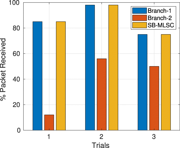
Branch-2 is partially covered with aluminum foil and, thus, receives lesser packets than branch 1. In this case, SB-MLSC tracks branch 1 which receives more packet than branch 2
-
2
The results corresponding to case 2 are plotted in Fig. 21. We performed three trials of the experiment (with different interference TXP) where we completely covered the receive antenna branch 1 with aluminum foil which effectively stopped branch 1 from receiving any WiFi frame. This resulted in SB-MLSC receiving the same number of WiFi packets as antenna branch 2, i.e., SB-MLSC again tracked the stronger branch and behaved as a selection combiner.
Fig. 21 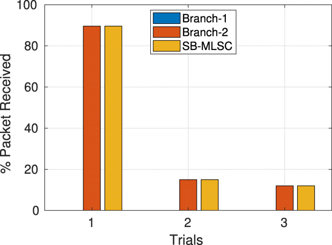
Branch 1 is fully covered with aluminum foil and hence ceases to receive any packet. In this case, SB-MLSC tracks branch 2 when branch 1 is killed
-
3
The results corresponding to case 3 are plotted in Fig. 22. We placed scrambled aluminum foils inside the RF cage to emulate multi-path reflections. We performed three trials of the experiment where we changed the positions of aluminum foils inside the RF cage. We indeed observe diversity gain for several placement scenarios of the scrambled aluminum foil although the gain was marginal.
Fig. 22 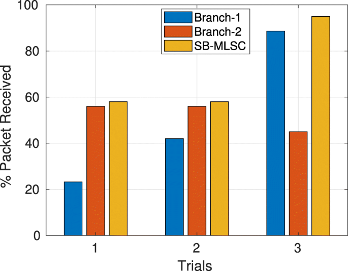
Scrambled aluminum foils are placed inside RF cage resulting in multi-path reflections. In this case, SB-MLSC provides diversity gain, i.e., receives more packet than both branch 1 and branch 2


Results corresponding to all the three cases of experiment 3 indicate the proper operation and tracking capability of SB-MLSC.
6 Conclusions
In this work, we have addressed the co-channel interference faced by wideband OFDM-based WiFi due to single/multiple narrowband ZigBee interferers in the 2.4-GHz ISM band. First, we describe single- and multi-antenna interference mitigating receiver architecture for WiFi which is based on the localized estimation of excess noise caused by single and multiple narrowband co-channel interferers. We also proposed a simple yet effective method for immediate detection of multiple narrowband interferers which is a by-product of our single-antenna method. Next, we extended our method for multi-antenna WiFi receivers and proposed MLSC which is the maximal-ratio combiner with LLR scaling. MLSC apart from interference mitigation also provides diversity gain. For both our methods—single- and multi-antenna—simulation results show significant SNR gain compared to conventional methods.
Further, we proposed SB-MLSC which is a soft-bit maximal-ratio combiner with LLR scaling. In simulations, SB-MLSC performs equivalently to MLSC in terms of diversity gain and interference mitigation; however, it is easy to implement. Finally, we implemented all our methods using USRP SDR and verified their functionality by performing over-the-air (OTA) tests using standard compliant WiFi and ZigBee frames. Results of OTA tests fall in agreement with our simulation results indicating the practical applicability of our methods. Our methods are applicable to all the wireless standards which are based on OFDM and face narrowband co-channel interference. All the methods we propose require modifications only on the receiver side, and hence they can be integrated into existing infrastructure with minimal modifications.
Availability of data and materials
Data sharing is not applicable to this article as no datasets were generated or analyzed during the current study.
Notes
In cellular networks, as the standards are homogeneous, there is only CCI and not CT-CCI
Table 1 contains simulation parameters for this figure.
We took the binary dump of WiFi and ZigBee frames generated by MATLAB and transmitted them using USRP SDR. The frames were detected by commercial WiFi and ZigBee nodes which established the standard compliance of the WiFi and ZigBee frames generated by MATLAB toolboxes
The last ZigBee channel affects only 5 subcarriers within the used subcarriers. The remaining two affect subcarriers, i.e., 53 and 54 are unused
OpenAirInterface WiFi Tx/Rx has been developed at Eurecom, France, and currently not available in public domain.
Abbreviations
- CCI:
-
Co-channel interference
- Conv-SC:
-
Conventional scaling
- CSMA/CA:
-
Carrier sense multiple access with collision avoidance
- ISM:
-
Industrial, scientific, and medical
- LLR:
-
Log-likelihood ratios
- LNV-SC:
-
Local noise variance LLR scaling
- LNV:
-
Local noise variance
- M2M:
-
Machine to machine
- MLSC:
-
Maximal-ratio combiner with LLR scaling
- OTA:
-
Over the air
- SB-MLSC:
-
Soft-bit maximal-ratio combining with LLR scaling
- SBMRC:
-
Soft-bit maximal-ratio combining
- SDR:
-
Software-defined radio
- SIC:
-
Successive Interference Cancelation
- TXP:
-
Transmit power
References
Y. Yubo, Y. Panlong, L. Xiangyang, T. Yue, Z. Lan, Y. Lizhao, in Proceedings of the 19th Annual International Conference on Mobile Computing & Networking. Zimo: Building cross-technology mimo to harmonize ZIGBEE smog with WIFI flash without intervention (ACMNew York, 2013), pp. 465–476.
Z. Zhao, X. Wu, X. Zhang, J. Zhao, X. -Y. Li, in Performance Computing and Communications Conference (IPCCC), 2014 IEEE International. ZIGBEE vs WIFI: Understanding issues and measuring performances of their coexistence (IEEEPiscataway, 2014), pp. 1–8.
Y. Yan, P. Yang, X. -Y. Li, Y. Zhang, J. Lu, L. You, J. Wang, J. Han, Y. Xiong, Wizbee: Wise ZIGBEE coexistence via interference cancellation with single antenna. IEEE Trans. Mob. Comput.14(12), 2590–2603 (2015).
S. -T. Sheu, Y. -Y. Shih, W. -T. Lee, Csma/cf protocol for ieee 802.15. 4 wpans. IEEE Trans. Veh. Technol.58(3), 1501–1516 (2008).
Y. -C. Tseng, S. -Y. Ni, E. -Y. Shih, Adaptive approaches to relieving broadcast storms in a wireless multihop mobile ad hoc network. IEEE Trans. Comput.52(5), 545–557 (2003).
C. -J. M. Liang, N. B. Priyantha, J. Liu, A. Terzis, in Proceedings of the 8th ACM Conference on Embedded Networked Sensor Systems. Surviving WIFI interference in low power ZIGBEE networks (ACMNew York, 2010), pp. 309–322.
A. Terzis, et al, Minimising the effect of WIFI interference in 802.15. 4 wireless sensor networks. Int. J. Sens. Netw.3(1), 43–54 (2007).
R. Xu, G. Shi, J. Luo, Z. Zhao, Y. Shu, in Internet of Things (iThings/CPSCom), 2011 International Conference on and 4th International Conference on Cyber, Physical and Social Computing. Muzi: Multi-channel ZIGBEE networks for avoiding WIFI interference (IEEE, 2011), pp. 323–329.
S. Kumar, F. Kaltenberger, A. Ramirez, B. Kloiber, in 2018 European Conference on Networks and Communications (EuCNC). A robust decoding method for OFDM systems under multiple co-channel narrowband interferers (IEEE, 2018), pp. 368–372.
S. Kumar, F. Kaltenberger, A. Ramirez, B. Kloiber, in WIMOB 2018, 14th International Conference on Wireless and Mobile Computing, Networking and Communications, 15-17 October 2018, Limassol, Cyprus. Robust OFDM diversity receiver under co-channel narrowband interference (Limassol, CHYPRE, 2018). http://www.eurecom.fr/publication/5654.
N. I. Miridakis, D. D. Vergados, A survey on the successive interference cancellation performance for single-antenna and multiple-antenna OFDM systems. IEEE Commun. Surv. Tutor.15(1), 312–335 (2013).
S. Sen, N. Santhapuri, R. R. Choudhury, S. Nelakuditi, Successive interference cancellation: Carving out mac layer opportunities. IEEE Trans. Mob. Comput.12(2), 346–357 (2013).
D. Halperin, T. Anderson, D. Wetherall, in Proceedings of the 14th ACM International Conference on Mobile Computing and Networking. Taking the sting out of carrier sense: interference cancellation for wireless lans (ACMNew York, 2008), pp. 339–350.
X. Zhang, K. G. Shin, Cooperative carrier signaling: Harmonizing coexisting wpan and wlan devices. IEEE/ACM Trans. Netw. (TON). 21(2), 426–439 (2013).
K. Pelechrinis, I. Broustis, S. V. Krishnamurthy, C. Gkantsidis, in Proceedings of the 5th International Conference on Emerging Networking Experiments and Technologies. Ares: an anti-jamming reinforcement system for 802.11 networks (ACMNew York, 2009), pp. 181–192.
K. Tan, H. Liu, J. Fang, W. Wang, J. Zhang, M. Chen, G. M. Voelker, in Proceedings of the 15th Annual International Conference on Mobile Computing and Networking. Sam: enabling practical spatial multiple access in wireless lan (ACMNew York, 2009), pp. 49–60.
S. Gollakota, S. D. Perli, D. Katabi, in ACM SIGCOMM Computer Communication Review, 39. Interference alignment and cancellation (ACMNew York, 2009), pp. 159–170.
B. -S. Seo, S. -G. Choi, J. -S. Cha, Maximum ratio combining for OFDM systems with cochannel interference. IEEE Trans. Consum. Electron.52(1), 87–91 (2006).
R. Ahmed, B. Eitel, J. Speidel, in Vehicular Technology Conference (VTC Spring), 2015 IEEE 81st. Enhanced maximum ratio combining for mobile dvb-t reception in doubly selective channels (IEEEPiscataway, 2015), pp. 1–5.
W. -C. Lee, C. -H. Cho, J. -H. Kwak, M. -Y. Park, K. -J. Kang, in Consumer Electronics, 1999. ICCE. International Conference On. Viterbi decoding method using channel state information in COFDM system (IEEEPiscataway, 1999), pp. 66–67.
S. Gollakota, F. Adib, D. Katabi, S. Seshan, in ACM SIGCOMM Computer Communication Review, 41. Clearing the rf smog: making 802.11 n robust to cross-technology interference (ACMNew York, 2011), pp. 170–181.
J. H. Winters, Optimum combining in digital mobile radio with cochannel interference. IEEE Trans. Veh. Technol.33(3), 144–155 (1984).
D. Croce, D. Garlisi, F. Giuliano, I. Tinnirello, in Ad Hoc Networking Workshop (MED-HOC-NET), 2014 13th Annual Mediterranean. Learning from errors: Detecting ZIGBEE interference in WIFI networks (IEEEPiscataway, 2014), pp. 158–163.
D. Croce, P. Gallo, D. Garlisi, F. Giuliano, S. Mangione, I. Tinnirello, in Wireless Communications and Mobile Computing Conference (IWCMC), 2014 International. Errorsense: Characterizing WIFI error patterns for detecting ZIGBEE interference (IEEE, 2014), pp. 447–452.
W. L. I. Agency, Ettus Research, an NI Brand. https://www.ettus.com/. Accessed 16 Nov 2018.
G. Radio, GNU Radio. https://www.gnuradio.org/. Accessed 16 Nov 2018.
F. Kaltenberger, X. Jiang, R. Knopp, in ASILOMAR 2017, Asilomar Conference on Signals, Systems, and Computers, October 29th-November 1st 2017, Pacific Grove, CA, USA. From massive MIMO to C-RAN: the OpenAirInterface 5G testbed (Pacific Grove, ÉTATS-UNIS, 2017). http://www.eurecom.fr/publication/5413.
IEEE Computer Society LAN MAN Standards Committee and others, Wireless lan medium access control (mac) and physical layer (phy) specifications. ANSI/IEEE Std. 802.11-1999, 24–26 (2003).
G. Ren, H. Zhang, Y. Chang, Snr estimation algorithm based on the preamble for OFDM systems in frequency selective channels. IEEE Trans. Commun.57(8) (2009).
AJ Viterbi, An intuitive justification and a simplified implementation of the map decoder for convolutional codes. IEEE J. Sel. Areas Commun.16(2), 260–264 (1998).
M. Sandell, F. Tosato, A. Ismail, Low complexity max-log llr computation for nonuniform pam constellations. IEEE Commun. Lett.20(5), 838–841 (2016).
L Tang, K Wang, Y Huang, F Gu, Channel Characterization and Link Quality Assessment of IEEE 802.15.4-Compliant Radio for Factory Environments. IEEE Transactions on Industrial Informatics. 3(2), 99–110 (2007).
A. Goldsmith, Wireless communications (Cambridge university press, Cambridge, 2005).
G. L. Stüber, Principles of mobile communication, vol. 2 (Springer, 1996).
B. Bloessl. IEEE 802.11 A/g/p Transceiver (BerlinSpringer. https://github.com/bastibl/gr-ieee802-11. Accessed 10 Nov 2018.
X. Ouyang, M. Ghosh, J. P. Meehan, Optimal antenna diversity combining for ieee 802.11 a system. IEEE Trans. Consum. Electron.48(3), 738–742 (2002).
A. B. Sediq, H. Yanikomeroglu, Performance analysis of soft-bit maximal ratio combining in cooperative relay networks. IEEE Trans. Wirel. Commun.8(10) (2009).
P. L. Kafle, A. Intarapanich, A. B. Sesay, J. McRory, R. J. Davies, Spatial correlation and capacity measurements for wideband mimo channels in indoor office environment. IEEE Trans. Wirel. Commun.7(5) (2008).
J. Cui, D. D. Falconer, A. U. Sheikh, Performance evaluation of optimum combining and maximal ratio combining in the presence of co-channel interference and channel correlation for wireless communication systems. Mob. Netw. Appl.2(4), 315–324 (1997).
S. Kumar, Soft Decision Viterbi Decoder for WIFI. https://github.com/sumitstop/SDVD-WiFi. Accessed 10 Nov 2018.
Acknowledgements
We are thankful to Dr. Alejandro Ramirez and Dr. Bernhard Kloiber from Siemens AG Corporate Technology, Munich, Germany, for their valuable feedback and review of the manuscript.
Funding
This work has received funding from Siemens AG Corporate Technology, Munich, Germany.
Author information
Authors and Affiliations
Contributions
SK carried out the theoretical studies, hardware implementation, and drafting the manuscript. FK participated in the software-defined radio implementation of the proposed methods. All authors read and approved the final manuscript.
Corresponding author
Ethics declarations
Competing interests
The authors declare that they have no competing interests.
Additional information
Publisher’s Note
Springer Nature remains neutral with regard to jurisdictional claims in published maps and institutional affiliations.
Rights and permissions
Open Access This article is distributed under the terms of the Creative Commons Attribution 4.0 International License(http://creativecommons.org/licenses/by/4.0/), which permits unrestricted use, distribution, and reproduction in any medium, provided you give appropriate credit to the original author(s) and the source, provide a link to the Creative Commons license, and indicate if changes were made.
About this article

Cite this article
Kumar, S., Kaltenberger, F., Ramirez, A. et al. An SDR implementation of WiFi receiver for mitigating multiple co-channel ZigBee interferers. J Wireless Com Network 2019, 224 (2019). https://doi.org/10.1186/s13638-019-1512-3
Received:
Accepted:
Published:
DOI: https://doi.org/10.1186/s13638-019-1512-3