- Research
- Open access
- Published:
Periodicity makes perfect: recovering interfered preamble for high-coexistence wireless systems
EURASIP Journal on Wireless Communications and Networking volume 2020, Article number: 45 (2020)
Abstract
Recent researches show that cross technology interference management plays an important role in the emergence of innovative applications for nowadays wireless networks. Existing algorithms either suffer from the constraint on the need of clean preamble or require technological similarities among cross technology systems. In this paper, we ask the question: “whether the packet with interfered preamble can be decoded?" To answer this question, we investigate the property of preamble and propose Narthil, an innovative coexistence algorithm which based on imperfect interference management, handling packet detection, symbol synchronization, and channel estimation with interfered preambles. Narthil applies a simple Butterworth band-stop filter for imperfect interference filtering, and leverages the residual signals for packet detection and symbol synchronization, as well as channel estimation. The insight is the inherent properties of preamble such as periodicity and modulation scheme, and the frequency continuity in OFDM signal could be effectively leveraged for important processes such as packet detection, symbol synchronization, and channel estimation. These favorable properties could be used to further enhance the performance of other cross technology signal coexistence algorithms. We implement Narthil algorithm on our USRP/GNU Radio platform, and evaluate its performance by using 15 USRP-N210 devices through the real deployment experiments. The results demonstrate that Narthil can effectively detect the incoming packet and achieves a high accuracy symbol synchronization, as well as channel estimation of the interfered preamble, and also achieve a good performance on packet decoding.
1 Introduction
Today’s advanced wireless technologies have witnessed the ubiquitous deployment of heterogeneous mobile networks, where cross technologies are vitally important when coexistence is becoming more and more pervasive than ever. Typical environmental monitoring systems, such as carbon dioxide monitoring program “CitySee”[1] deployed in Wuxi, China, and “Smart Earth”[2] have shown the feasibility of aforementioned complex and large-scale system. Image a smart home, where various sensors exchange their data through ZigBee network, user uses his computer to access the Internet via WiFi, and the mouse and keyboard he used are connected to the computer via the Bluetooth interface.
In that, many densely deployed wireless networks are working in heterogeneous mode at the same ISM band, which is overcrowded because of the occupancy of WiFi, ZigBee, Bluetooth networks, etc. In homogeneous networks, the collisions and interferences between devices can be solved or mitigated by using protocols such as CSMA/CA. Unfortunately, in the heterogeneous network, the devices follow various protocols and are hard to communicate and cooperate with each other. Therefore, the confliction and interference are unavoidable and the performance of whole ISM band drops consequently. Assigning different frequency bands to different networks or let devices transmit their packet alternatively is an intuitive way. However, with the increasing of network nodes, the bottleneck of such methods will quickly emerge since the limited time and spectrum resoures. By designing the suitable algorithm, nodes of different networks can simultaneously transmit their signals in the same band, which can effectively improve the spectrum utilization and throughput of the whole networks. Most of the relevant works [3–7] focus on coordinating the heterogeneous signals with advanced interference management technology. For example, WizBee [6] exploits the inherent diversity of WiFi and ZigBee signals, making efforts in decoding WiFi signals with higher strength and treating ZigBee signal with lower strength as noise in temporary. Since there is only one antenna applied to WizBee, the ZigBee packet should be decoded after careful interference cancelation of the WiFi packet. ZIMO [5] on the other hand leverages the basic fact that not all preambles are distorted when a packet collision occurs, and makes efforts in eliminating the packet with clean preamble. Leveraging the interference nullifying technology, ZIMO could effectively decode the remained clean packet. After that, a carefully designed interference cancelation algorithm is incorporated to cancel out the decoded packet to ensure the successful decoding of the foregoing nullified packet.
Although these studies have successfully resolve the heterogeneous interference management problem, the unresolvable limitations still exist. Dependencies on bootstrapping procedure hinder the applicability and tolerability of the existing methods. For example, WizBee [6] needs a relatively large energy gap (at least 15 dB) to guarantee its performance and could not work well when deployment is dense. Moreover, ZIMO [5] requires at least one interference-free preamble from both collided packets to begin the processing; however, the clean preamble is hardly available when the interference is extremely high. Actually, all these algorithms mentioned above are limited by the constraint of clean preamble.
In this paper, we first analyze the reason why the receiver failed to decode in the case of interfered preamble, and deeply investigate the relationship between the periodicity of short training symbols (STS) and the frequency spacing between adjacent subcarriers. Based on our findings, we propose Narthil, a novel method to mitigate this constraintFootnote 1. Narthil exploits the advantage of STS, which can be used to perform packet detection, symbol synchronization, and CSI estimation, without the need of clean preamble. Moreover, Narthil can decode the collided WiFi and ZigBee packets consequently.
In order to achieve these goals, two simple but effective methods are used to cope with indispensable challenges. The first challenge is how to detect the incoming packet and synchronize the received symbol. When preamble is interfered, the periodicity of its training symbols is destroyed, which leads to the failures in packet detection and symbol synchronization. To cope with this challenge, Narthil exploits the periodicity of short training symbols and proposes a periodicity recovery algorithm, which can recover the corrupted periodicity in preamble by filtering out the interference, ensuring the high performance on packet detection and symbol synchronization algorithm as well.
The second challenge we have to cope with is how to achieve a precise channel estimation. Narthil leverages the diversity in bandwidth bewteen WiFi and ZigBee signals, and the frequency continuity of OFDM signal. Specifically, WiFi bears a 10 times larger bandwidth than ZigBee, which means that only fractional subcarriers of WiFi are interfered by ZigBee. Based on this fact, Narthil can interpolate the CSI across all interfere-free subcarriers to estimate the CSI of the interfered subcarriers.
We implement Narthil algorithm on our USRP/GNU Radio platform and validate our design with intensive evaluations. Both WiFi and ZigBee transmissions are carefully scheduled to ensure both preambles are interfered. Comparing with other state of arts coexistence algorithms, Narthil can achieve above 94% and 97% accuracy in packet detection and symbol synchronizations, respectively. The channel estimation and packet decoding also show a considerably high performance.
In summary, this paper makes three major contributions:
We analyze the causes of packet decoding failure in the scenario of heterogeneous interference, and study the relationship between the periodicity of preamble and the frequency spacing among adjacent subcarriers. We find that, by carefully filtering out the interfered subcarrier, the destroyed periodicity of short training symbols could be effectively recovered. This inspiring insight could be effectively leveraged for packet detection, symbol synchronization, and channel estimation. We believe that, such discovery could be further applied to other cross-technology-concerned coexistence networks, especially when interfered preambles are involved.
We propose Narthil, an algorithm that breaks through the constraint of clean preamble. Narthil can successfully perform packet detection, symbol synchronization, and CSI estimation without the clean preamble and achieves favorable performance on packet decoding of both WiFi and ZigBee. To the best of our knowledge, it is the first method to work effectively with the interfered preambles of coexisting signals.
We implement Narthil on our USRP platform, and test its performance on both micro-benchmarks and macro-benchmarks with intensive experiments. The experimental results show that Narthil can achieve a 100% accuracy on both packet detection and symbol synchronization, with the precisely estimated CSI, Narthil can achieve a nearly 100% and 80% of packet delivery ratio on WiFi and ZigBee, respectively.
The rest of this paper is organized as follows: We show some preliminaries in Section 2 and investigate the inherent property of preamble in Section 3; then, we illustrate our algorithm in Section 4 and show the experiment study in Section 5. After that, we introduce some related work in Section 6. Finally, we conclude our work in Section 7.
2 Preliminaries
2.1 Preamble primer
We first introduce some primary information about the preamble. Preamble is a sequence of known symbols sent before data transmission. It provides a period and information for several receiver functions such as packet detection, symbol synchronization and channel estimation. Preamble typically uses a robust modulation scheme that can be decoded even at low SNR values. The format of IEEE 802.11a preamble is shown in Fig. 1, which consists of Short Training Symbols (STS) and Long Training Symbols (LTS), where STS is used for the packet detection and LTS is used for symbol synchronization, as well as channel estimation. One special property of STS in the time domain is that STS includes ten periods, consisting of 16 samples for each one.

Preamble format of IEEE 802.11a
Preamble plays an extremely important role in both WiFi and ZigBee communications. An interfered preamble will cause an error incoming packet judgment and let the receiver drop the packet directly. Besides, the interfered preamble results in symbol synchronization failure and produces severe errors on channel estimation. Both of them will degrade the decoding performance of receiver significantly. So in the coexistence of WiFi and ZigBee networks, both signals are unknown additional noise. As a result, even ZigBee packet overlaps with a part of WiFi bandwidth, it still interferes the WiFi preamble and causes WiFi decoding fail. Similarly, when a ZigBee preamble is interfered with WiFi packet, the ZigBee receiver also cannot decode such interfered ZigBee packet.
2.2 802.11 Packet detection
Wireless sensor network is essentially a random access network, where the receiver does not know exactly whether and when a packet comes. To achieve this goal, it first measures the energy of the received signal rx as
where L is the length of the sliding window and ∗ represents the complex conjugate of the signal. If mn is higher than a given threshold, it means the packet presents and receiver applies “delay and correlate algorithm” to synchronize the incoming packet and see whether it is a WiFi packet.
This approach takes advantage of the periodicity of the short training symbols. As Fig. 2 illustrates, two sliding time windows C and P are consisted in this algorithm. The C window is a cross-correlation between the received signal and its delayed version:

Signal flow structure of the delay and correlate algorithm
where D is the period of short training symbols.
The P window calculates the received signal energy during the cross-correlation window:
The value of P window is used to normalize the decision statistic, so that is not dependent on absolute received power level.
Receiver can find the frame start position based on the maximum value of the above equation, where |·|2 and (·)2 denote the module-square operation and square operation, respectively.
Specifically, since the STS contains 10 copies of 160 samples, the value of decn should be greater than a given threshold value, and the lasting time should at least half of the STS duration, as shown in Fig. 3. Receiver measures the lasting time of decn, and determines whether the incoming packet is a WiFi packet, and serves the start point of such high value as the frame start position.

Use delay and correlate algorithm to synchronize the incoming packet
3 Investigation of preamble
3.1 Periodicity of training symbols
3.1.1 Periodicity of short training symbol
In WiFi communication, receiver applies delay and correlate algorithm which we discussed above to detect the incoming packet. This approach takes advantage of the periodicity of short training symbols, which contain ten identical duplicates. Each duplicate is modulated by the predefined sequence S,
and the waveform is generated according to the following equation:
where wTSHORT is the time-windowing function, NST is the number of subcarriers, and Δf is the subcarrier frequency spacing, which is 312.5 kHz.
As Fig. 4b illustrated, a short training symbol utilizes 12 out of 52 subcarriers, and the frequency spacing among non-zero amplitude subcarriers is ΔF=4Δf, which results in a periodicity of TFFT/4, i.e., 16 symbols (see Fig. 4a), where TFFT=1/Δf.

Periodicity of STS is destroyed by the interference. a Clean STS sequence. b FFT of clean STS. c Interfered STS sequence. d FFT of interfered STS
3.1.2 Corruption of periodicity
The periodicity of short training symbols can be easily corrupted when packet collision occurs, especially when the interference signal overlapped with some subcarriers of the target signal. In this case, the interference signal will lead to a significant change on the amplitude of received STS, as well as its frequency spacing. Specifically, it causes the ΔF dropping to zero and makes the period close to infinity, i.e., destroying its periodicity. Moreover, As the interference signal is also carrying data, it can be regarded as additive white Gaussian noise and thus makes STS nonidentical and the periodicity corrupted consequently. Figure 4c and d show the corruption of periodicity of short training symbols in both time and frequency domain.
When the periodicity of short training symbols is corrupted, the packet detection algorithm based on such periodicity fails and the packet is lost consequently.
3.1.3 Periodicity recovery
Equation 6 illustrates that the periodicity depends directly on the subcarrier frequency spacing ΔF, as a result, to find a way to recover the periodicity of STS sequence, we first need to investigate how the subcarrier frequency spacing ΔF affects the period of STS sequence. For this reason, a series of simulations are conducted to investigate the relationship between ΔF and period of STS sequence.
The first simulation is conducted to validate whether there is a periodicity of STS if only two subcarriers exist, and how the period changes with various subcarrier frequency spacing ΔF. In this simulation, only two non-zero subcarriers are retained, and we modify the frequency spacing between them. Then, the corresponding STS sequence is generated and we estimate its period. The results are shown in Fig. 5, where Δf is the frequency spacing between two adjacent subcarriers and ΔF is the frequency spacing between two adjacent non-zero subcarriers.

Observation 1: the period of STS is determined by subcarrier frequency spacing ΔF. aΔF=4Δf, bΔF=8Δf, cΔF=12Δf, dΔF=16Δf, eΔF=20Δf, fΔF=24Δf, gΔF=28Δf, hΔF=40Δf, iΔF=44Δf
As Fig. 5 shows, the STS sequence keeps its periodicity throughout the simulation. As Fig. 5 a, b, and d illustrate, when ΔF becomes larger, the period of STS sequence becomes smaller, which is tally with Eq. 6. Moreover, the relationship between period of STS and ΔF can be expressed by the following equation.
The TSTS is the period of STS sequence, and takes a symbol as a unit.
We note that, in some simulations, such as Fig. 5 c, e, f, and h, the results are not matched with Eq. 7 well. This is because when we put these ΔFs into the Eq. 7, the calculated results are not integers but fractions such as \(\frac {16}{x}\), where x is an odd number. Thus, the period of such STS sequence cannot be estimated directly in denomination of symbols. As a result, the actual measured period of STS sequence \(T_{\text {STS}}^{'}\) is composed of x periods, which causes the actual measured period \(T_{\text {STS}}^{'}\) is 16 symbols.
In the next simulation, we keep the subcarriers on one sideband unchanged, but filter various number of consecutive subcarriers on the other sideband to investigate whether these filtered subcarriers will have an impact on the period of STS sequence. The results are shown in Fig. 6. As we can see, the period of training symbols is stable throughout the simulation. We suspect that this phenomenon may derive from the unchanged frequency spacings on the remained sideband.

Observation 2: filtering some consecutive subcarriers out does not change the period of STS. a Filter subcarrier no. 24. b Filter subcarrier no. 20 and 24. c Filter subcarrier no. 16, 20, and 24. d Filter subcarrier no. 12, 16, 20, and 24. e Filter subcarrier no. 8, 12, 16, 20, and 24. f Filter subcarrier no. 4, 8, 12, 16, 20, and 24
In order to validate our assumption, another two simulations are conducted. In the first simulation, we keep one sideband of subcarriers unchanged, but filter out the other sideband of subcarriers discontinuously to obtain various frequency spacings. In the second simulation, the subcarriers on both sidebands are filtered out, except for a portion of some consecutive subcarriers. The results are shown in Figs. 7 and 8.

Observation 3: filtering some non-contiguous subcarriers in one sideband out does not change period of STS. a Filter subcarrier No. 8, 16, 24. b Filter subcarrier No. 8, 12, 20, 24

Observation 4: filtering some non-contiguous subcarriers in both sidebands out does not change period of STS. a Filter subcarrier No. -8, 8, 16. b Filter subcarrier No. -12, -8, 8, 12, 20, 24. c Filter subcarrier No. -16, -12, -8, 8, 12, 16, 20, 24
These simulations validate our assumption, and show that the period of short training symbols is determined by the minimum frequency spacing over all subcarriers. This phenomenon can be interpreted as follows: when the frequency spacing between adjacent non-zero amplitude subcarriers changes, only the periods associated with those two subcarriers are affected. We note that, the period of whole short training symbols is determined by the least common multiple (LCM) of the periods among all adjacent subcarriers. This means that the period of short training symbols is only related to the smallest frequency spacing between adjacent non-zero amplitude subcarrier, i.e., 16 symbols in WiFi preamble.
Based on the simulations above, we can get the following conclusions.
The period of the short training symbol sequence is related to the frequency spacing between adjacent non-zero amplitude subcarriers.
When the frequency spacings among adjacent non-zero amplitude subcarriers are equal, the period of STS sequence can be calculated by \(T_{\text {STS}} = \frac {64}{\Delta _{F}}\), where 64 is the total number of subcarriers, and ΔF is the frequency spacing between adjacent non-zero amplitude subcarriers.
When the frequency spacings among adjacent non-zero amplitude subcarriers are not equal, the period of STS sequence is determined by the least common multiple of the period among all adjacent subcarriers.
As a result, we can easily recover the destroyed periodicity of training symbols by making the normal frequency spacing be the smallest ones. Briefly, we filter those interfered subcarriers out. Figure 9 illustrates the effectiveness of this method.

After filtered interfered subcarriers out, the periodicity of short training symbols is recovered. a FFT of filtered STS. b Filtered STS sequence
4 System design
4.1 System overview
Based on the deep investigation of preamble’s periodicity we discussed above, we propose an innovative coexistence scheme, Narthil, which can perform the packet detection, symbol synchronization without the presents of clean preamble, Narthil can further estimate the channel state information in the absence of clean preamble and decodes the collided packets consequently.
Figure 10 provides the overview of Narthil, where three modules are included: (1) Packet detection and symbol synchronization module, which is used to detect an incoming packet and performs fine symbol synchronization in the absence of clean preamble; (2) ZigBee decoding module, which is used to estimate the CSI of WiFi packet and further decode ZigBee packet; and (3) WiFi decoding module, which is used to decode WiFi packet via nullifying ZigBee packet.

Algorithm diagram
When the interfered packets are received, the receiver first detects the start point of WiFi packet and performs symbol synchronization of WiFi packet. Then it estimates the CSI of such WiFi packet and leverages the estimated CSI to nullify WiFi packet from the interfered packets. Thus, the ZigBee packet can be decoded easily. After that, the receiver nullifies ZigBee packet and decodes WiFi packet consequently.
4.2 Algorithm in detail
4.2.1 Packet detection and synchronization
4.2.1.1 Filter customization
As Fig. 11 shows, each WiFi channel is likely to overlap with four ZigBee channels, the receiver should know exactly which channel the ZigBee packet occupies in order to be able to effectively filter out the interference. Narthil leverages the fact that, comparing with WiFi packet, ZigBee packet has a much longer lasting time; thus, receiver can easily identify which channel ZigBee occupied by scanning the spectrum when WiFi transmission is idle. As Fig. 12 illustrates, receiver determines the channel occupied by ZigBee packet by measuring the spectrum occupancy in the period indicated by the green box. Then, the channel information of such ZigBee packet will be used to set the parameters of the band-stop filter to filter ZigBee interference out and to recover the destroyed periodicity of WiFi preamble.

WiFi and ZigBee channels

The different packet lasting time between WiFi and ZigBee provides the opportunity to identify the interfered channel
4.2.1.2 Packet detection
After we recover the destroyed periodicity of WiFi preamble, the packet detection algorithm will be able to work effectively. Figure 13 shows that, after filtering out the interference, Narthil can accurately detect the incoming packet.

Interference filtering helps packet detection. a Packet detection before filtering. b Packet detection after filtering
We note that in Fig. 13b, there is another peak at the end of the WiFi packet, which marked in a green circle, except for the peak that we want to represent the start of the WiFi packet, which is marked in a red circle. This extra peak is due to the huge energy gap at the end of the WiFi packet, so it is easy to be identified.
4.2.1.3 Packet synchronization
Packet detection only provides a limited resolution estimation of starting edge of an incoming packet. To obtain a symbolic level precision, receiver uses a simple cross-correlation-based symbol timing algorithm. Specifically, receiver calculates the cross-correlation of the received signal rn and an known reference signal tk, i.e., the long training symbols (LTS).
The value of n that corresponds to maximum absolute value of the cross-correlation is the symbol timing estimate. Specifically, since the LTS consists of two identical copies, there are two peaks appear after cross-correlation, and 64 symbols are separated from each other, as Fig. 14 shows. We use the first peak as the exact symbol timing estimate.

Symbol synchronization by using modified LTS
However, in our scenario, the preamble of the received WiFi packet has been partially filtered out, so using Eq. 8 may not be able to get the desired result and will introduce synchronization error. Narthil solved this problem by rebuilding an LTS that matched the filtered WiFi preamble.
Specifically, the receiver sets the value of subcarriers in the standard LTS sequence which corresponding to the stopband of band-stop filter to zero, and uses the modified LTS sequence for packet synchronization. The result can also be seen in Fig. 14.
4.2.2 ZigBee decoding
4.2.2.1 Channel estimation
Another important step associated with packet decoding is the channel state estimation. As Eq. 9 shows, receiver estimates channel coefficient by comparing the received long training symbols (LTS) with the known after performing a DFT process.
where \(\hat {H_{k}}\) is the estimated channel coefficient, Xk is one LTS sequence, and R1,k and R2,k are two received LTS, respectively. By calculating the mean of R1,k and R2,k, it is possible to reduce the interference of the ambient noise for accurate estimation.
However, the channel coefficient cannot be calculated directly in our scenario, since the received LTS is either distorted by ZigBee interference or partly filtered out by the band-stop filter. Moreover, in order to achieve precise symbol synchronization, the reference LTS sequence also does a similar filtering process. The CSI estimated by using received LTS is shown in Fig. 15 a and b, respectively. To cope with this problem, two important properties of OFDM signal are leveraged. The first property is that, comparing with ZigBee, WiFi signal has more than 10 times wider bandwidth, as a result, not all subcarriers of WiFi packet are affected by ZigBee interference. The other important feature is the frequency continuity of OFDM signal, specifically, the frequency response among adjacent subcarriers is continuous, which means that the CSIs of adjacent subcarriers are interrelated. Narthil leverages both properties and interpolates the CSI across all interfere-free subcarriers to estimate the CSI of interfered ones. Figure 15 c shows the result of our modified channel estimation algorithm, in which the red dash line is the estimated CSI of interfered subcarriers.

Channel estimation. a CSI before filter. b CSI after filter. c CSI after interpolation
4.2.2.2 WiFi nullification
In order to obtain an interference-free ZigBee packet, we first need to remove the WiFi packet from the received overlapped signals. On a dual antenna receiver, antennas are coupled together and their received signals can be expressed as follows:
where y1 and y2 are the received signals on each antenna, W(t) and Z(t) are the transmitted WiFi and ZigBee signals, respectively, and hij serves as channel coefficients among different transmitter-receiver pairs. In our scenario, h11 and h12, which are the CSI of WiFi packet on each antenna, have been obtained in the previous section. Thus, the interference nullifying processing can be used for ZigBee alignment, as Eq. 11 shows.
By subtracting the two equations above, the WiFi component of the received overlapped signal can be eliminated, and the ZigBee signal can be expressed by:
This interference-free ZigBee packet can be decoded easily. Figure 16 shows the received signal before and after we perform WiFi nullification, respectively. From such figures, we can easily see that, after WiFi nullification, the WiFi packet has been almost eliminated, and left only a negligible residual noise which will not cause serious interference on ZigBee decoding.

Performance of WiFi nullification. a Original received signal. b WiFi has been nullified
4.2.2.3 ZigBee decoding
After that, a standard ZigBee decoder is designed according to IEEE 802.15.4. When the interference-free ZigBee packet is fed into the decoder, it should be down-sampled first due to the large gap of sampling rate between WiFi and ZigBee receiver. Then, SFD (start frame delimiter) will be found via autocorrelation operation, and frequency offset is compensated via a phase-locked loop (PLL). Next, receiver resolves the phase ambiguity and performs timing recovery too. After all, OQPSK demodulation, chip to symbol decoding are performed subsequently, and the CRC is calculated for verifying correctness of this packet. We recommend readers to read the IEEE 802.15.4 [9] for a more detailed description.
4.2.3 WiFi decoding
4.2.3.1 Clean signal identification
To mitigate the impact of ZigBee interference on WiFi decoding, we leverage the diversity of lasting time between WiFi and ZigBee packets. Specifically, we estimate the channel response of ZigBee when WiFi transmission is idle, as the green box shown in Fig. 12, and use these channel responses to nullify ZigBee interference. As we already know which period the WiFi packet exists (see Fig. 13b), it is easy to identify which period only the ZigBee signal exists.
4.2.3.2 ZigBee nullification
In the period which only ZigBee packet exists, the Eq. 10 can be rewritten as follows since there is no WiFi component exists.
Based on Eq. 13, we can calculate the channel response ratio of the received signal between different antennas of the receiver, named β.
We assume the channel state is stable over the ZigBee transmission time, then we can use β to cancel the ZigBee packet from the received signal, and get the undisturbed WiFi packet.
We illustrate the performance of our ZigBee nullification algorithm in Fig. 17. As we can see, after ZigBee nullification, the SINR of WiFi packet has been increased.

Performance of ZigBee nullification. a Original received cignal. b ZigBee has been nullified
4.2.3.3 WiFi decoding
According to IEEE 802.11g, to decode a WiFi packet, receiver should find the STS and LTS of such packet first, and perform frequency offset compensation, channel estimation consequently, and decode the signal field to determine the modulation type and coderate, as well as the number of octets in the PSDU. After that, demodulation processing is applied, followed by chip to symbol decoding and CRC checking consequently. We also recommend readers to read the IEEE 802.11 [10] for a more detailed description.
5 Performance evaluation
5.1 Experiment setup
To evaluate the performance of our algorithm, we implement Narthil on our GNURadio/USRP N210 software radio platform. In our implement, two USRP devices are used as WiFi and ZigBee transmitters to send WiFi and ZigBee packets, respectively, and the other two USRP devices are connected via a MIMO cable as a dual antenna receiver. The experimental data are collected in real time and processed with Matlab.
We show in detail the parameters of experiments in Table 1. We implement the OFDM PHY layer of WiFi and OQPSK PHY layer of ZigBee, the bandwidths of WiFi and ZigBee are 20 MHz and 2 MHz, respectively. The center frequency of WiFi and ZigBee are chosen in 2.342 GHz and 2.430 GHz, respectively. We select the WiFi and ZigBee payload length to be 256 B and 20 B, respectively.
In order to evaluate the performance of our algorithm in the case of the interfered preamble, we need to collect packets with collided preamble. As a result, it is non-trivial to synchronize two USRPs, since the packet collision happens in signal-level. We exploit the time stamp mechanism provided by GNURadio community to deliberately create the WiFi/ZigBee collision. The transmission cycle of both WiFi and ZigBee have been carefully adjusted to ensure that both preambles are subjected to interference.
To provide a better understanding of the performance of our algorithm, we set a series of signal power ratio. For brevity, we set the ZigBee signal received power fixed at 8 dBm, and WiFi signal received power from 5 dBm adjusted to 25 dBm. We repeat the experiments 5 times for each parameter configurations, and in each time, 100 WiFi packets and 100 ZigBee packets are transmitted.
5.2 Evaluation
We evaluate Narthil’s performance in our GNURadio/USRP software radio testbed in realistic environments. We conduct micro-benchmark to evaluate three key aspects of Narthil, including packet detection, symbol synchronization, and CSI estimation. We then show the benefit of Narthil for coexisted networks, by comparing the throughput gain of Narthil with some state of the art coexistence scheme [5].
5.2.1 Micro-benchmark evaluation
5.2.1.1 Performance of packet detection
We first evaluate the performance of our packet detection algorithm since packet detection is the first and most important task of the receiver. Since the failure of packet detection will lead to packet loss, it is easy to evaluate the performance of packet detection algorithm. Specifically, we count the number of packets which are identified by the receiver, and compare it with our original setting, i.e., 100 packets per times. All the identified packet numbers are collected and the statistical results are shown in Fig. 18. The closer the number of packets identified by the receiver to the actual number of transmitted packet, the better the performance of the packet detection algorithm.

System performance of packet detection and symbol synchronization. a Performance of packet detection. b Performance of symbol synchronization
As this figure shows, the accuracy of our packet detection can always be above 94%, and achieves nearly 100% when WiFi’s signal strength is above 9 dBm.
5.2.1.2 Symbol synchronization
The second benchmark we tested is the performance of symbol synchronization. The measurement method is as follows: since one of the important functions of preamble is to delineate the signal field, which defines the code rate and modulation, as well as the length of payload of the received packet, we use the decoded signal field to determine whether our symbol synchronization performs well or poor. Specifically, the signal field is followed by the preamble sequence, any symbol synchronization error will affect the signal field positioning, and thus lead to an error information of code rate, modulation, and the length of payload of the received packet. We check the decoded signal field information, such as code rate and modulation, then comparing them with our pre-set parameters. The mismatch of the decoded parameter and pre-set parameter indicates the error of symbol synchronization, and vice versa. The statistical results are shown in Fig. 18b.
As Fig. 18b illustrated, the accuracy of our symbol synchronization is always above 97% and achieves nearly 100% when WiFi’s signal strength is above 9 dBm, which means our symbol synchronization algorithm meets the need of packet decoding.
5.2.1.3 CSI estimation
The last benchmark we investigate is the performance of CSI estimation. CSI plays an important role in packet decoding. Without an accurate CSI, receiver can hardly decode the packet correctly. To evaluate the performance of CSI estimation algorithm, we deliberately create a clean WiFi packet. We first estimate the exact CSI by using the WiFi preamble and serve this CSI as the reference value. Then, we filter out the partial subcarriers of the WiFi packet and estimate the channel response of such filtered subcarriers by using our CSI estimation algorithm. Finally, we compared the estimated CSI with the reference value in both real part, and imaginary part of the CSI value. The performance of our CSI estimation algorithm is shown in Fig. 19, where the blue solid line represents the reference CSI value which we calculated by using WiFi’s clean preamble, and the red dash line represents the calculated CSI which we estimated by using our CSI estimation algorithm. As Fig. 19 shows, both lines are very close, thus demonstrating that our CSI recovery algorithm performs well.

Performance of CSI recovery. a Real part of CSI. b Image part of CSI
5.2.2 System performance evaluation
In this section, we conduct two sets of experiments to evaluate the performance of our algorithm. We first study the algorithm performance in the absence of clean preamble, and comparing it with ZIMO, the start-of-art cross-tech coexistence algorithm. Then, we compare the performance of both algorithms in a more general case, where preambles of both WiFi and ZigBee packets are not always collided. The experimental results are shown below.
5.2.2.1 System performance in the absence of clean preamble
We first evaluate the performance of our system in the absence of clean preamble. In this study, the parameter configurations are shown in Table 1. We set the received WiFi signal power in various levels while fixed the received ZigBee signal power to study how our system performs in different WiFi/ZigBee power ratio cases. We repeat the experiments 5 times for each parameter configurations, and for each time, 100 WiFi packets and 100 ZigBee packets are transmitted. The received signals are then collected and processed via Narthil and ZIMO, respectively.
Figure 20 shows the performance of packet delivery ratio when we use Narthil and ZIMO, respectively. In this set of experiments, ZIMO cannot decode any packet for either WiFi or ZigBee, since there is no clean preamble can be used for packet detection. While Narthil achieves a good PDR performance for both WiFi and ZigBee, which the average ratios are nearly 100% and 80%, respectively.

System performance in the absents of clean preamble. a WiFi decoding performance. b ZigBee decoding performance
We note that, comparing with the performance of ZigBee decoding, Narthil performs better in WiFi decoding. This phenomenon comes from the difference between WiFi nullification algorithm and ZigBee nullification algorithm. Specifically, to nullify a WiFi interference, Narthil should estimate WiFi’s CSI. Therefore, the imperfect channel estimation may cause some residual WiFi interference which may degrade the ZigBee decoding. On the other hand, when Narthil performs ZigBee nullification, there is no WiFi interference; thus, the ZigBee interference can be nullified more completely, which results in a better decoding performance.
5.2.2.2 System performance in typical interference scenarios
We conduct the other set of experiments in the typical interference scenario, where the preamble of WiFi and ZigBee are not always collided with each other, in order to make a better understanding of the performance of our algorithm.
In this scenario, the interference can be divided into four types according to various situations of preamble, i.e., the preamble of WiFi packet is clean, the packet of ZigBee packet is clean, the packets of both WiFi and ZigBee packets are clean, and no preamble of either WiFi or ZigBee packet is clean. Figure 21 shows the experiment results. As the figure shows, the WiFi decoding performance of ZIMO increases with the received WiFi signal power, while Narthil always experiences a good WiFi decoding performance which is around 95%. This is because compared with ZIMO algorithm which uses ZigBee’s preamble to nullify ZigBee interference, Narthil can use a much longer ZigBee sequence in calculating the channel response ratio, β, which can achieve a better channel estimation when the received WiFi signal power is weak and thus achieves a better ZigBee nullification performance. When the received signal power of WiFi is increasing, the residual ZigBee interference can no longer affect WiFi decoding and both algorithms have a similar performance consequently.

System performance in typical interference scenarios. a WiFi decoding performance. b ZigBee decoding performance
On the other hand, the performance of ZigBee decoding of ZIMO is poorer than Narthil, compared with the nearly 90% PDR of Narthil, ZIMO only achieves the PDR of 40%. This is derived from the basic fact that when the only ZigBee packet has a clean preamble, to decode ZigBee packet, ZIMO has to decode WiFi signal first and regenerates the received WiFi packet for interference cancelation. Unfortunately, any failure of either step will cause a ZigBee decoding failure consequently. Considering the lasting time of both WiFi packet and ZigBee packet, this problem will often occur, and thus causes the degradation of ZigBee decoding in ZIMO. The ZigBee decoding of Narthil on the other hand is independent with WiFi decoding and can achieve a relatively higher performance.
We also compared the performance of Narthil and ZIMO in the case of clean WiFi/ZigBee preamble. In this experiment, we carefully adjusted the transmission time and interval of WiFi and ZigBee, deliberately generated overlapped signals with clean wifi preamble and clean zigbee preamble, respectively. Figure 22 shows the decoding performance of both Narthil and ZIMO with clean WiFi preamble and clean ZigBee preamble, respectively. From such figure, we can find the following:
When there is a clean WiFi/ZigBee preamble, the ZigBee/WiFi decoding performance of ZIMO will be improved.
Fig. 22 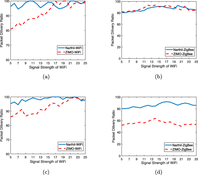
Performance comparison with clean WiFi/ZigBee preamble. a WiFi decoding performance with clean WiFi preamble. b ZigBee decoding performance with clean WiFi preamble. c WiFi decoding performance with clean ZigBee preamble. d ZigBee decoding performance with clean ZigBee preamble
The clean WiFi preamble has a greater impact on ZigBee decoding of ZIMO.
The preamble has no obvious impact on the performance of Narthil.

This is because of the following:
ZIMO uses interference nullification and cancelation in turn to eliminate the impact of both signals to each other. Compared to the interference nullification, the interference cancelation introduces more noises and thus causes the degradation of packet decoding.
Clean preamble helps improve the performance of interference nullification, allowing another signal to be decoded better.
Compared to zigbee, the WiFi signal’s power is stronger and causes more serious interfrence on ZigBee decoding.
Narthil is designed to solve the coexistence problem when preambles are distorted. Therefore, the condition of preamble causes no impact on Narthil’s performance.
Furthermore, we compared the performance of Narthil and WizBee under different SNR gaps between WiFi and ZigBee. Figure 23 shows the experiment result. As such figure illustrates, When the SNR is low, WizBee cannot decode any WiFi or ZigBee packet. and when SNR exceeds 10 dB, the PDR of WizBee starts to increase. While Narthil’s performance is consistently stable at different SNRs. This is because WizBee needs a relatively large energy gap to guarantee its performance; when WiFi signal is too weak, it is hard for WizBee to decode WiFi packet, and the subsequent steps fail consequently. Narthil, on the other hand, does not rely on energy gap. Therefore, it works well even when WiFi signal is weak than ZigBee.

Performance comparison with WizBee. a WiFi decoding performance. b ZigBee decoding performance
6 Discussion
The management of heterogenous interference is widely concerned in today’s wireless signal coexistence researches. The most direct way to address the coexistence problem is frequency planning [11–14] or temporal scheduling [15–18]. However, these methods require a centralized controller. Meanwhile, only three orthogonal WiFi channels are available in 2.4 GHz ISM band, densely deployed WiFi networks will make interference-free frequency planning fail. Moreover, these densely deployed communication nodes make temporal scheduling inefficiently and reduce the throughput of networks as well.
Many studies were presented to tackle the co-channel concurrent coexistence issue. Most of these studies treat WiFi as the interested signal, while other overlapped signals are eliminated as interference. TIMO [7] proposes a WiFi-aware receiver design which treats ZigBee transmissions as interference, as well as microwave and other unknown interference. By leveraging the silent duration between adjacent WiFi transmissions, TIMO can nullify ZigBee interference and decode WiFi easily. However, high-speed WiFi transmission is suppressed by the ZigBee nullification and will reduce the network performance. However, TIMO [7] only concerns the performance of WiFi network and sacrifices ZigBee communication. Moreover, the high-speed WiFi transmission is suppressed by the ZigBee nullification, and the network throughput is reduced consequently. Narthil, on the other hand, can ensure the network performance of both WiFi and ZigBee.
Some other researches [19, 20] aim at canceling ZigBee interference out by estimating the interference component in all subcarriers of WiFi. Jamadagni [21] proposes a mathematical model of ZigBee interference and then estimate and cancel ZigBee interference from WiFi later. However, this algorithm still needs more experimental evidence instead of simulation.
Inspiring works WizBee [6] and ZIMO [5], devote to recovering both information from overlapped WiFi and ZigBee packets. WizBee exploits the energy diversity between WiFi and ZigBee, treat ZigBee signal as noise and attempt to decode WiFi first, followed by WiFi cancelation and ZigBee decoding. ZIMO [5] leverages the frequency and temporal diversity to resolve the coexistence problem. Unfortunately, WizBee only works well when large energy diversity is available and ZIMO serves clean preamble as a crucial premise. Compared to them, Narthil does not require huge energy diversity or the the preamble integrality, and can be applied to more scenarios.
Qiu et al. [22] develop a novel system to enable coexistence between LTE and WiFi without the need of clean preamble or interfering signals from either WiFi or LTE transmission. The main contribution of this work is the channel estimation without clean preamble or interfering signals. However, both LTE and WiFi are OFDM modulated signal, which is different from our problem.
Bayhan et al. [23] leverages the space domain and time domain, by performing the cooperation between neighboring LTE-U and WiFi networks, a coordinated coexistence scheme is proposed. But the cooperation between LTE-U and WiFi nodes is needed, which is unavailable in today’s COTS devices. AccuEst [24] propose an accurate corruption estimation approach to mitigate the interference on ZigBee network. ART [25] and ATE [26] also achieve the purpose of interference avoidance of ZigBee communication by measuring or estimating the utilization of the channel. However, these methods only solves the problem of conflict detection without solving the impact of the conflict. Narthil, on the other hand, solves the impact of interference on communications and effectively improves spectrum utilization.
7 Conclusion
In this paper, we first analyze the causes of packet loss in heterogeneous interference, and study the relationship between the periodicity of preamble and the frequency spacing among adjacent subcarriers. We find that, by filtering out the interfered subcarrier, the destroyed periodicity of short training symbols can be recovered. Based on such research, we propose a filter-based cross technology signal coexistence algorithm, called Narthil. Narthil can break through the constraint of the need of clean preamble in packet decoding. It can precisely detect the incoming packet with the interfered preamble, and achieve almost 100% symbol synchronization, as well as CSI estimation. Moreover, Narthil can decode both interfered WiFi and ZigBee packets in parallel.
We implement Narthil on our USRP/GNU software radio platform and evaluate its performance in detail. The experimental result shows that Narthil can achieve an accuracy over 94% and over 97% in packet detection and symbol synchronization, respectively, and can estimate the CSI pretty well. The further studies show that Narthil also has a good packet decoding performance on both WiFi and ZigBee. The experimental results show that, Narthil can achieve a 100% packet delivery ratio on WiFi and an 80% on ZigBee packet. To the best of our knowledge, Narthil is the first attempt to break through the constraint of the need of clean preamble, and the first filter-based algorithm to resolve such cross technology coexistence problems. We claim that this inspiring design policy could be further leveraged for other cross technology signals.
Notes
An earlier version of this paper was presented at the 2nd International Conference on Cloud Computing and Security [8].
References
X. Mao, X. Miao, Y. He, et al., in 2012 Proceedings IEEE INFOCOM. CitySee: Urban CO 2 monitoring with sensors (IEEE, 2012), pp. 1611–1619.
Smart earth website (2012). http://www.smartearth.org. Accessed 2012.
Zhiguo, John, Keeney, Sebastian, Robitzsch, Faisal, Zaman, Xiaojun, Wang, Multilevel pattern mining architecture for automatic network monitoring in heterogeneous wireless communication networks. China Commun.13(7), 108–116 (2016).
K. Tan, H. Liu, J. Fang, et al., in Proceedings of the 15th annual international conference on Mobile computing and networking. SAM: enabling practical spatial multiple access in wireless LAN, (2009), pp. 49–60.
Y. Yubo, Y. Panlong, L. Xiangyang, et al., in Proceedings of the 19th annual international conference on Mobile computing & networking. Zimo: Building cross-technology mimo to harmonize zigbee smog with wifi flash without intervention, (2013), pp. 465–476.
Y. Yan, P. Yang, X. Y. Li, et al., Wizbee: Wise zigbee coexistence via interference cancellation with single antenna. IEEE Trans. Mob. Comput.14(12), 2590–2603 (2014).
S. Gollakota, F. Adib, D. Katabi, et al., in Proceedings of the ACM SIGCOMM 2011 conference. Clearing the RF smog: making 802.11 n robust to cross-technology interference, (2011), pp. 170–181.
P. Li, P. Yang, Y. Yan, et al., in International Conference on Cloud Computing and Security. Narthil: Push the limit of cross technology coexistence for interfered preambles (SpringerCham, 2016), pp. 92–104.
IEEE. IEEE Standard for Information Technology.Local and Metropolitan Area Networks. Specific Requirements. Part 15.4: Wireless Medium Access Control (MAC) and Physical Layer (PHY) Specifications for Low Rate Wireless Personal Area Networks (WPANs), Standard 802.15.4-2006. (2006).
LAN/MAN Committee. IEEE Std 802.11-2007: IEEE Standard for Information Technology- Telecommunications and Information Exchange between Systems-Local and Metropolitan Area Networks-Specific Requirements Part 11: Wireless LAN Medium Access Control (MAC) and Physical Layer (PHY) Specifications. (IEEE Computer Society, 2007).
C. Won, J. Youn, H. Ali, et al., in IEEE Vehicular Technology Conference. Adaptive radio channel allocation for supporting coexistence of 802.15. 4 and 802.11 b (IEEE, 2005).
S. Pollin, M. Ergen, M. Timmers, et al., in 2006 1st International Conference on Cognitive Radio Oriented Wireless Networks and Communications. Distributed cognitive coexistence of 802.15. 4 with 802.11 (IEEE, 2006), pp. 1–5.
L. Tang, Y. Sun, O. Gurewitz, et al., in Proceedings of the Twelfth ACM International Symposium on Mobile Ad Hoc Networking and Computing. EM-MAC: a dynamic multichannel energy-efficient MAC protocol for wireless sensor networks, (2011), pp. 1–11.
R. Xu, G. Shi, J. Luo, et al., in 2011 International Conference on Internet of Things and 4th International Conference on Cyber, Physical and Social Computing. Muzi: Multi-channel zigbee networks for avoiding wifi interference (IEEE, 2011), pp. 323–329.
X. Zhang, K. G. Shin, in Proceedings of the Twelfth ACM International Symposium on Mobile Ad Hoc Networking and Computing. Enabling coexistence of heterogeneous wireless systems: Case for ZigBee and WiFi, (2011), pp. 1–11.
S. Lim, S. Lee, J. Yoo, et al., NBP: light-weight narrow band protection for ZigBee and Wi-Fi coexistence. EURASIP J. Wirel. Commun. Netw.2013(1), 76 (2013).
L. Angrisani, M. Bertocco, D. Fortin, et al., Experimental study of coexistence issues between IEEE 802.11 b and IEEE 802.15. 4 wireless networks. IEEE Trans. Instrum. Meas.57(8), 1514–1523 (2008).
J. Huang, G. Xing, G. Zhou, et al., in The 18th IEEE International Conference on Network Protocols. Beyond co-existence: Exploiting WiFi white space for Zigbee performance assurance (IEEE, 2010), pp. 305–314.
Doufexi, A. Arumugam, S. Armour, A. Nix, An investigation of the impact of bluetooth interference on the performance of 802.11g. Wirel. Local Area Networks. 1:, 680–684 (2003).
D. Zhang, P. Fan, Z. Cao, A novel narrowband interference canceller for OFDM systems. in Proc. IEEE WCNC. 3:, 1426–1430 (2004).
M. Roy, H. S. Jamadagni, Cancellation of Zigbee interference in OFDM based WLAN for multipath channel. ACEEE Int. J. Netw. Secur.1(01), 35–39 (2011).
S. Yun, L. Qiu, in 2015 IEEE Conference on Computer Communications (INFOCOM). Supporting WiFi and LTE co-existence (IEEE, 2015), pp. 810–818.
S. Bayhan, A. Zubow, A. Wolisz, in 2018 IEEE 19th International Symposium on" A World of Wireless, Mobile and Multimedia Networks"(WoWMoM). Coexistence gaps in space via interference nulling for LTE-U/WiFi coexistence (IEEE, 2018), pp. 1–10.
G. Chen, W. Dong, Z. Zhao, et al., Accurate Corruption Estimation in ZigBee under Cross- Technology Interference. IEEE Trans. Mobile Comput.18(10), 2243–2256 (2018).
F. Li, J. Luo, G. Shi, Y. He, Art: Adaptive frequency-temporal co-existing of zigbee and wifi. IEEE Trans. Mobile Comput.16(3), 662–674 (2016).
Y. Sun, Z. Qin, J. Hu, et al., in International Conference on Wireless Algorithms, Systems, and Applications. Enabling ZigBee Link Performance Robust Under Cross- Technology Interference (SpringerCham, 2018), pp. 450–461.
Acknowledgements
This research is partially supported by 2017YFB0801702, National Key Research and Development Plan; NSFC with no. 61772546, 61632010, 61232018, 61371118, 61402009, 61672038, and 61520106007; China National Funds for Distinguished Young Scientists with no. 61625205; Key Research Program of Frontier Sciences, CAS, No. QYZDY-SSW-JSC002, and NSF OF Jiangsu For Distinguished Young Scientist: BK20150030.
Author information
Authors and Affiliations
Contributions
PL carried out the basic idea, designed the system, performed the experiment study, and drafted the manuscript. PY conceived of the study, and participated in its design and coordination and helped to draft the manuscript. YY participated in the design of the study. All authors read and approved the final manuscript.
Corresponding author
Ethics declarations
Competing interests
The authors declare that they have no competing interests.
Additional information
Publisher’s Note
Springer Nature remains neutral with regard to jurisdictional claims in published maps and institutional affiliations.
Rights and permissions
Open Access This article is distributed under the terms of the Creative Commons Attribution 4.0 International License(http://creativecommons.org/licenses/by/4.0/), which permits unrestricted use, distribution, and reproduction in any medium, provided you give appropriate credit to the original author(s) and the source, provide a link to the Creative Commons license, and indicate if changes were made.
About this article

Cite this article
Li, P., Yang, P. & Yan, Y. Periodicity makes perfect: recovering interfered preamble for high-coexistence wireless systems. J Wireless Com Network 2020, 45 (2020). https://doi.org/10.1186/s13638-019-1621-z
Received:
Accepted:
Published:
DOI: https://doi.org/10.1186/s13638-019-1621-z