- Research
- Open access
- Published:
Two-level frame precoding with non-cooperative gateways
EURASIP Journal on Wireless Communications and Networking volume 2020, Article number: 151 (2020)
Abstract
This paper considers the pre-processing design to mitigate the multibeam interference in the downlink of a high-throughput satellite, with a common precoder for several users sharing the same frame, and limited adaptation capabilities on-board the satellite. Beams are grouped in clusters managed by different non-cooperative gateways. A two-level approach is performed, with an on-board beamforming network complemented by on-ground precoders. The former, designed with the SLNR (signal-to-leakage and noise ratio) criterion, mitigates the inter-cluster interference, whereas the latter fight the intra-cluster multiuser co-channel interference. Judicious user scheduling is also addressed to limit the impact of the multicasting and limited adaptation capabilities. Several two-level precoding designs can be obtained by setting accordingly the degree of cooperation and the frame adaptation, with an overall satisfactory performance with respect to the single-gateway benchmark. In particular, a sector-based solution with non-cooperative gateways presents a good trade-off between gateway autonomy and performance.
1 Introduction
The increasing demand for communication throughput is pushing the technology, also in the case of space. High-throughput satellites (HTS) are steadily gaining prevalence, operating on mature multibeam technology, with bandwidth carefully shared by the different beams to keep co-channel interference at low levels [1]. However, the ever-growing traffic demand is pressing for more efficient ways of allocating the scarce power and bandwidth resources. Exploitation of the whole bandwidth by all beams is being considered as a way forward to very high-throughput satellites (V/HTS). This aggressive full frequency reuse scheme gives rise to strong co-channel interference, making it necessary to implement advanced cancelation schemes such as linear precoding at the transmit side [2–4], or the adoption of multiuser detection (MUD) receivers [5–9].
The use of precoding for the satellite forward link finds some practical challenges, some of which have been deeply studied in the literature [4, 10]. For instance, long forward error correction codewords accommodating information bits for several users are at the core of the physical layer of the DVB-S2 standard. The multiplexing of information addressed to users with different channels under the same physical layer frame requires the use of multicast precoding [10, 11], which can be adopted for practical use after the introduction of the super-frame structure in the recent DVB-S2X standard [12, 13]. Additionally, the selection of users and how they are grouped becomes highly relevant for the performance of precoding; in this regard, user scheduling has been also the object of different recent publications [3, 14–16].
New V/HTS are expected to multiply the current offered throughput by a single satellite without the corresponding increase of the feeder link bandwidth. As a consequence, additional links are required between the ground and the satellite, with multiple gateways (GWs) to be employed so that the feeder link does not become a bottleneck. Even though frequencies above the Ka-band are used, such as Q/V-band, W-band, or optical [17–20], several ground stations are still required due to the associated challenges of a unique gateway able to provide high throughputs with the required availability. Thus, it is not uncommon to find some active ground stations operating the same satellite, with some other additional idle ground stations for redundancy. In the case of optical feeder links, a unique ground station suffices to channelize the entire throughput. However, the use of additional active optical ground stations can reduce the investment on the ground segment [20].
A satellite coverage is usually formed by several beams that illuminate a given Earth region for a specific service. In the multiple gateway operation, the coverage is split into different groups of beams, labeled as clusters. Each cluster service is assigned to a different gateway that employs a given subset of radiating elements, also known as feeds, that are available in the satellite. Under full frequency reuse (FFR), all on-board radiating elements use the same frequency band, rising the co-channel interference levels. Due to the multiple gateway operation, two types of co-channel interference can be defined: (i) intra-cluster interference due to the neighboring beams within the same cluster and (ii) inter-cluster interference, caused by the signals addressed to users in other clusters. This multiple gateway scenario is depicted in Fig. 1. The user signals transmitted by the gateways can be precoded to mitigate the co-channel interference, with the challenge of finding an effective and practical design. The mitigation of the inter-cluster interference may require the exchange of information or the joint design of the precoders across gateways, thus increasing the complexity of the ground segment. In addition, frame precoding is also required for satellite communications due to the long forward error codewords. By frame precoding, we will refer to the linear operation performed on the transmit symbols to mitigate the co-channel interference at the receivers, when several users in a given beam are served by one codeword for each channel use. Frame precoding with multiple gateways was initially analyzed in [21] and more recently in [22]. In both cases, cooperation among the gateways was assumed for the design of the precoders.

Multiple gateway scenario
In this paper, our objective is to explore the performance limits of multiple gateway precoding solutions when gateways do not communicate with each other, conditioned by the frame operation mode. We will detail further and extend our preliminary results on two-level precoding presented in [23], therein without frame constraints. The two-level precoder is formed by both an inner precoder, which is designed to fight the intra-cluster interference, and an outer precoder, which is in charge of limiting the inter-cluster interference (see Fig. 2). To some extent, connections with two-level interference mitigation schemes for terrestrial systems can be made. This concept has been pursued in the literature under different names: two-stage beamforming [24], hierarchical interference mitigation [25], or two-tier precoding [26]. The common ground is to design an outer beamformer to address the inter-group interference, whereas an inner precoder performs the intra-group multiplexing. These ideas can be traced back to [27] and [28], where dimensionality reduction techniques were proposed for massive MIMO systems: a pre-beamforming stage applies an approximate block diagonalization based on second-order statistics. Thus, no real-time feedback of the channel values is required to track the slow variation of the spatial correlation. Caire et al. applied these ideas to a single cell setting, generalizing the concept of sectorization commonly employed in cellular deployments, to grouping based on second-order statistics. Other works such as [25] and [26] applied similar ideas to multiple interfering base stations. More recently, the case of multiple cells and a multilayer precoding structure, combining also instantaneous channel knowledge and average statistics, was pursued in [29].

Two-level precoding structure. The outer precoder B operates on-board the satellite, whereas the inner precoder T is on the gateway
The current work presents a two-level interference cancelation scheme for the downlink of a multibeam satellite, which is managed by multiple gateways. An outer precoder on-board the satellite is designed based on the SLNR (signal-to-leakage and noise ratio) criterion, previously proposed in the literature for other multiuser scenarios [30–32]. This on-board beamforming network is complemented by inner precoders at the gateways, which operate with instantaneous local channel information and global statistics, and do not require the exchange of information among the gateways, thus simplifying the ground segment. Frame-based precoding is addressed to multiplex several intra-beam users within the same channel use, so that multicast designs need to be developed for each level. Interestingly, the nature of the blueproposed two-level precoding is such that an independent approach for each level can be pursued, so that the degree of adaptation, the required channel information, and the users which are considered can differ from one level to the other. The preliminary work in [23] has been extended in this paper to provide a more general two-level precoder framework that enables multicast transmissions to support frame constraints. In addition, this framework allows to build new two-level precoder designs by setting different degrees of adaptation for each level.
After presenting the system model in Section 3, the implementation of two-level frame precoding is described in Section 4. After that, the numerical results and conclusions are given in Sections 5 and 6, respectively.
Notation: Upper (lower) boldface letters denote matrices (vectors). (.)H, (.)T, tr{·}, IN, and diag{·} denote Hermitian transpose, transpose, matrix trace operator, N×N identity matrix, and diagonal matrix, respectively. \(\mathbb {E}\left [ {\cdot }\right ]\) is the expected value operator.
2 Methods
The sum mean-square error (SMSE) and SLNR criteria are combined to build different types of two-level frame precoders. The satellite frame constraints and limited on-board adaptation capabilities are taken into account for the design process. The proposed designs are tested under a real multibeam diagram pattern; Monte Carlo simulations are employed to model the effect of the random location of the users.
3 System model
In this work, we focus on the forward link of a multibeam satellite communication system with multiple gateways. Let Q denote the number of beams filling up the satellite coverage and M the number of gateways in the system. The spots-beam in the coverage are divided into M different groups, known as clusters, each served by a different gateway, as represented in Fig. 1. Thus, \(k=\frac {Q}{M}\) beams are assigned to each gatewayFootnote 1. The satellite has N radiating elements or feeds to serve the beams, with N≥Q. To serve each cluster, the gateways have access to a different subset of n satellite feeds, with n≥k, such that the groups of n feeds are not necessarily disjoint. We assume an ideal feeder link between the gateways and the satellite, and a beamforming network (BFN) in the satellite that synthesizes the received signals from the gateways to relay them to the users in the coverage. Each subset of feeds has an available power Pm for its respective cluster. This power restriction is based on the use of an active antenna array with multiport amplifiers [20], so that the power can be shared among those amplifiers serving a given cluster.
We use \(\mathbf {H}_{m,p} \in \mathbb {C}^{k \times n}\) to denote the channel between the n satellite feeds operated by the pth gateway and the k beams in the mth cluster. Thus, Hm,m ∀m denotes the channel between the satellite feeds operated by the mth gateway and its assigned cluster, and Hm,p ∀m≠p denotes the channel that contains the inter-cluster interference in the mth cluster that is caused by the satellite feeds operated by the pth gateway. The (r,l)th entry of the matrix Hm,p is given by:
Here, Grl represents the transmit antenna gain from the lth feed to the corresponding location in the r-h beam. As for the rest of the terms, GR refers to the receive antenna gain; λ is the carrier wavelength; kB denotes the Boltzmann constant; T and W are the clear sky noise temperature of the receiver and the user link bandwidth, respectively; ϕrl is the phase rotation introduced by the channel; and dr is the distance from the satellite to the user in the rth beam of the mth cluster.
The information from each gateway is encoded and grouped in the vectors of symbols \(\mathbf {s}_{m} \in {\mathbb {C}}^{k\times 1}, m=1,\ldots,M\), normalized as \(\mathbb {E}\left [ {\mathbf {s}_{m} \mathbf {s}_{m}^{H} }\right ] =\mathbf {I}_{k} \), which is linearly processed by the two-level precoder Fm. In the unicast case, k users per cluster are simultaneously served, one per beam; the received signals and noise are collected in the vectors \({\mathbf {y}}_{m}, {\mathbf {n}}_{m} \in {\mathbb C}^{k\times 1}, m=1,\ldots,M\), respectively. The noise nm is a zero-mean unit variance additive white Gaussian noise (AWGN), such that \(\mathbb {E}\left [ {\mathbf {n}_{m} \mathbf {n}_{m}^{H}}\right ] = \mathbf {I}_{k}\). The two-level precoder \(\mathbf {F}_{m} \in \mathbb {C}^{n \times k}, m=1,\ldots,M\) is composed by an outer precoder \(\mathbf {B}_{m} \in \mathbb {C}^{n \times k}, m=1,\ldots,M\), and an inner precoder \(\mathbf {T}_{m} \in \mathbb {C}^{k \times k}, m=1,\ldots,M\), with Fm=BmTm, as per Fig. 2. The system input-output relation can be written as:
The on-board beamforming matrices Bm are the outer precoders, whereas the processing taking place at the ground gateways is featured by the inner precoding matrices Tm. If the gateways communicate directly with the radiating satellite feeds, then Fm is entirely implemented at the mth gateway, in what it is known as on-ground beamforming (OGBF) [22], and which will not be considered here.
In the multicast case, more than one user per beam gets data from the same frame; this group of NG users shares the same two-level precoder. This precoder can be fully or partially reused across different frame transmissions, corresponding to a number NU of users. The relation between NU and NG will be detailed at each level when designing the two-level precoder. Similarly to [10], we extend the notation (2) to address the multicast case. Thus, the signals for the ith user in a given beam are collected as:
where i=1,…,NU. Now, \(\mathbf {y}_{m}^{[i]},\, \mathbf {n}_{m}^{[i]} \in {\mathbb C}^{k\times 1}, m=1,\ldots,M\) are the received signal vector and the noise vector of the ith user in the mth cluster, respectively.
The signal-to-interference plus noise ratio (SINR) of the ith user in the bth beam from the mth cluster will be determined by the poorest channel of all those served by the same frame, with:
where fb,m is the bth column of the matrix Fm, \(\mathbf {w}_{b,m}^{[i]}\) is the bth row of the matrix \(\mathbf {H}_{m,m}^{[i]}\), and \(\mathbf {v}_{d,m,p}^{[i]}\) is the dth row of the matrix \(\mathbf {H}_{m,p}^{[i]} \). The maximization of the SINR is a very complex task, with M coupled variables Fm to be designed. This is why we will operate in the next section with a more convenient metric, computed as the ratio of the intra-cluster signal power to the off-cluster leaked interference plus noise [30].
4 Two-level frame precoding
The grouping of users to be served by the same frame is based on the similarity of the corresponding channels, in order to limit the degradation with respect to the unicast case [3]. As an example, Fig. 3 illustrates a particular case with M=2 clusters and k=2 beams per cluster. In each beam, different groups X of users are formed with X={A,B,C,D} so that the groups with the same label across the beams are addressed simultaneously. The different groups are served in consecutive frames by employing the precoder Fm[X], with m∈{1,2} denoting the corresponding cluster. For the sake of clarity in the design process, we drop the dependence of the precoder on the user group and denote the two-level precoder as Fm.

Multicast setting. a User grouping. b Frame structure
Next, we will detail how to design the two-level precoders Fm as a two-step process, starting with the outer precoders Bm which operate in the satellite and following with the inner precoders Tm in the gateways. We derive first the expressions for the outer precoder and inner precoder for the multicast case. The design will be made for a specific selection of users and will be such that it can be tailored to the amount of available channel information. Then, different two-level strategies are presented exploiting the flexibility in the two-level design.
4.1 Outer precoder
The outer precoders {Bm} are designed to minimize the inter-cluster interference. For that purpose, the intra-cluster signal strength to the off-cluster leaked interference plus noise (SLNR) is set as the optimization criterion. Thus, we do not address the highly non-convex SINR optimization which would be required to minimize simultaneously the intra-cluster and inter-cluster interference. Initially, let us assume that the design is made for a group of NG users sharing the precoder. Then, the inter-cluster interference power posed by the mth gateway on the k users of cluster p with multicast index i is given by \(\mathbb {E}\{\|{\mathbf {H}_{p,m}^{{[i]} }}\mathbf {F}_{m} \mathbf {s}_{m}\|^{2}\}\), so that the total off-cluster leakage on the users with multicast index i reads as:
where the expectation is taken with respect to the transmitted symbols sm, and \(\widetilde {\mathbf {H}}_{m}^{[i]}\) is the matrix that comprises the channels from the mth gateway to users with multicast index i in the rest of clusters:
Then, the overall inter-cluster interference to the group of NG users sharing the precoder can be written as:
On the other hand, the total power received by those users in the mth cluster with multicast index i from the mth gateway can be expressed as:
The received power can be accumulated for all users which are simultaneously served to yield:
Now, we can define the overall SLNR metric of the mth gateway as:
Then, the SLNR optimization problem reads as:
with the matrices (Gramians) \({\mathcal {G}}_{m}\) and \(\widetilde {\mathcal {G}}_{m}\) defined as:
The optimization problem from (11) is such that the power constraint at the solution is not necessarily active, at least for some gateways. However, for reasons that will become more clear later in the paper, the identification of that solution requires the exchange of information among gateways. In consequence, we will use the maximum available power at the gateways, in the understanding that the optimality loss is the price to pay for an autonomous operation. Thus, we can rephrase the problem as:
where \(\mu _{m} = \frac {k}{P_{m}}\). This constrained bound for the SLNR will be used to drive the design of the two-level precoder Fm.
For convenience, we drop the subindex m and write henceforth \({\mathcal {G}}_{m}\), \(\widetilde {\mathcal {G}}_{m}\), Fm, and μm in (14) simply as \({\mathcal {G}}\), \(\widetilde {\mathcal {G}}\), F, and μ, respectively. We exploit the generalized eigenvalue decomposition (GEVD):
where Γ is n×n positive (semi-)definite diagonal with the generalized eigenvalues (in descending order), and the columns of Z comprise the generalized eigenvectors. Then, it holds that \(\mathbf {Z}^{H} {\mathcal {G}} \mathbf {Z} =\mathbf \Gamma \) and \(\mathbf {Z}^{H} (\widetilde {\mathcal {G}} + \mu \cdot \mathbf {I}_{n}) \mathbf {Z} =\mathbf {I}_{n}\) [33]. Letting now ¶=Z−1F, with (economy-sizeFootnote 2) SVD ¶=USVH, one has:
which does not depend on V. It can be easily shown that (16) is maximized with respect to S (diagonal positive semidefinite) and U (semi-unitary) when \(\mathbf {S} = \alpha \mathbf {e}_{1} \mathbf {e}_{1}^{H}\) and \(\mathbf {U} = [\begin {array}{cc} \mathbf {e}_{1} & \mathbf {U}_{0} \end {array}]\), where α>0 is chosen to satisfy the power constraint, e1 is the first element of the canonical basis (of appropriate dimension), and U0 is an arbitrary n×(k−1) semi-unitary matrix such that \(\mathbf {U}_{0}^{H}\mathbf {e}_{1} = \boldsymbol {0}\). However, this yields the rank 1 matrix:
Hence, the overall channel HmF=HmZ¶ from gateway m to its intended users would also have rank 1, clearly unsufficient to support k intra-cluster users requiring k independent streams.
To avoid this undesired effect, we may fix S=αIk, in which case (16) becomes simply tr{UHΓU}/k. Maximizing this with respect to U semi-unitary, the optimum is found to be \(\mathbf {U} = \left [\begin {array}{c} \mathbf {I}_{k} \\ \boldsymbol {0} \end {array}\right ]\), yielding \( \P = \alpha \left [\begin {array}{c} \mathbf {V}^{H} \\ \boldsymbol {0} \end {array}\right ], \) which now has full rank k. The precoder-beamformer matrix becomes F=αZ¶=αZ1VH, where Z1 is n×k and comprises the first k columns of Z.
The splitting of F=BT as the product of the outer and inner precoders can be pursued in different ways; for example, if we want B to be semi-unitary, we use the SVD \(\mathbf {Z}_{1}=\mathbf {U}_{1}\mathbf {S}_{1} \mathbf {V}_{1}^{H}\) and then take B=U1 and \(\mathbf {T} = \alpha \mathbf {S}_{1}\mathbf {V}_{1}^{H} \mathbf {V}^{H}\).
The previous design is oriented to causing as little inter-cluster interference as possible to other gateways’ users, but it does not take into account the intra-cluster interference. It is not clear that the constrained factorization of the inner precoding matrix as \(\mathbf {T} = \alpha \mathbf {S}_{1}\mathbf {V}_{1}^{H} \mathbf {V}^{H}\) will be able to help fight this intra-cluster interference. In fact, some simulations showed us that this is not necessarily the case. In consequence, we make a practical approach to obtain the two-level precoder, and decouple the design of both precoders. We keep the outer precoder design as B=U1 from the SLNR optimization problem to reduce the inter-cluster interference, and design an inner precoder which takes also into account the inter-cluster interference. The combined outer-inner precoder will no longer be optimal under the SLNR criterion in (14), but will be able to mitigate also the intra-cluster interference, so that the global balance will be positive as the simulations confirmFootnote 3. Additionally, this design makes it possible an autonomous operation of the gateways and leaves additional degrees of freedom to mitigate the intra-cluster interference, as detailed next.
Interestingly, the splitting of the two-level precoder provides some valuable freedom for the design process. For instance, the rate of adaptation does not have to be necessarily the same for the inner and the outer precoders and may remain fixed for several frames. In practice, it may not be feasible to optimize Fm to the specific channel realization. If we assume on-board beamforming (OBBF), the outer precoder can be seen as a beamforming network. The maximization of (10) would require the permanent adaptation of the BFN, which might be too demanding for the payload. If the BFN remains fixed for r frames, then the outer precoder Bm would be designed for a number of users NU=r·NG. In the limit, for a completely fixed BFN, i.e., unbounded r, the Gramian matrices in (12) and (13) are approximated as:
where the expectation is taken with respect to the channel matrices.
4.2 Inner precoder
The inner precoder needs to be designed to reduce the intra-cluster interference, conditioned by the operation in an environment with inter-cluster interference. We will introduce first the expressions for the unicast case, taken from [22], to be extended afterwards for the multicast case.
4.2.1 Unicast case
The design criterion is based on the minimization of the SMSE, computed as the aggregation for all clusters of the squared error between transmit symbols sm and estimated values at receivers \(\hat {\mathbf {s}}_{m}\):
with
We assume that end users cannot cooperate and that all receivers in the same cluster apply a common normalization factor:
with \(1/\sqrt {t_{m}}\) the scaling applied by users in cluster m. Therefore, the SMSE can be expressed as:
After the optimization process, the inter-cluster aware unicast precoder is given by [22]:
with
Interestingly, the optimal regularization factor is proved to be γm=k/Pm in [22] if the power constraint is active. Furthermore, we can avoid the dependence of Σm on the scaling factors in other clusters if we approximate Σm as:
where the different scaling factors {tm} have been assumed to be similar. Yet, this design still requires the coordination of the different gateways to exchange their respective channel state information (CSI) matrices. An autonomous design of the different precoders, based solely on the instantaneous intra-cluster channel information Hm,m, is feasible if the inter-cluster channel Gramians in Σm are replaced by their corresponding expectations, so that:
Now, the gateways only rely on local CSI and some second-order statistics of the channel that are assumed to be known beforehand.
4.2.2 Multicast case
The extension of the precoder design to the multicast case requires the redefinition of the sum mean-square error in (20), to accommodate NU simultaneous users per beam:
with
For the multicast design, we assume a different inner precoder per frame, so that NU=NG in the design process of the inner precoder.
By working with (29), we have:
The minimization of SMSE in (31) is equivalent to the corresponding unicast problem in (23), if the average channel matrices and average Gramians of all the involved user channels are used instead. In consequence, the inter-cluster aware multicast precoder is given by:
with
The optimal regularization factor is easily seen to be now equal to γm=kNU/Pm if the power constraint is active. The proof for the regularization factor in [22] can also be used for the multicast case since the problem presents a similar structure. The equivalent expressions to (27) and (28) read now as:
if cooperation among gateways is feasible, and
for autonomous operation.
4.3 Flexible two-level design
As mentioned earlier in the section, the two-level design affords some flexibility: different group sizes can be chosen at each level by setting the corresponding NU accordingly. Thus, the outer precoder and/or the inner precoder can be reused in different frame transmissions if required, with possibly different update rates in both cases. Thus, the two-level precoder Fm could remain fixed, at least partially, for some groups of users in the mth cluster. Before delving into the different strategies for the updating rates, let us address the user scheduling process and its interplay with the framing structure.
4.3.1 User scheduling
Scheduling has a twofold role, namely the grouping of users at each beam to be served by the same frame, and the matching of groups at different beams to be precoded simultaneously. The latter can be addressed by the Geographical Scheduling Algorithm (GSA) from [15]: beams are divided into sectors, so that only groups in the same relative position (sector) at different beams are served simultaneously. Thus, users in different beams are guaranteed to keep a minimum separation for the sake of the precoding scheme. The scheduling process is such that the sectors are served sequentially in time, and similarly for the different user groups inside each sector. Users are grouped by following a clustering algorithm; in this regard, we have chosen the MaxDist clustering from [14], which tries to minimize the inter-group distance by dealing with the most isolated user in the sector. Thus, if beams are divided into four sectors as in Fig. 4, the initial example in Fig. 3 is transformed into the scenario in Fig. 5 with GSA.

Beams are divided into four sectors. The sectors with the same numeration are served at the same time

Multicast scenario with groups formed with the Geographical Scheduling Algorithm (GSA)
4.3.2 Two-level design
We consider that the inner precoders will be computed on a frame basis, since gateways are expected to use real-time CSI for the permanent adaptation of the linear precoders. As opposed, configurability of the on-board outer precoder, or BFN, is usually quite limited, so that real-time adaptation is rarely feasible. Thus, different update requirements can be set by designing the outer precoder for the corresponding NU values. For illustration purposes, Fig. 5 shows four groups of users in the same sector. A different inner precoder Tm[X] will be designed for each of the four groups, with X={A,B,C,D}. On the other side, the outer precoder Bm will be updated on a time-scale which might fall under one of the following categories:
-
Adaptive design. The outer precoder is adapted on a frame basis, following the design from (12) and (13). Real-time cooperation among the gateways is required to exchange the CSI to compute the precoders. The update rate can be relaxed if the same outer precoder is designed for a number of r>1 consecutive frames, with NU=r·NG. For illustration purposes, Fig. 6 illustrates three different update rates for the outer precoder, namely at every frame, at every other frame, and once in four frames. Note that the inner precoder is designed on a frame basis. For those cases for which the outer precoder is fixed for several frame transmissions, the MaxDist clustering can be also used to determine which groups are going to be served by the same outer precoder. In the limit, a sector-based outer precoder is common for all the groups inside the same sector in Fig. 7, as detailed next.
Fig. 6 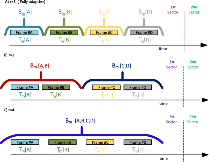
Adaptive designs for different levels of adaptation within the sector
Fig. 7 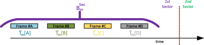
Sector-based design for the outer precoder
-
Sector-based design. In the limit, when NU grows very large, the adaptive design boils down to a sector-based design, and rather than instantaneous CSI, second-order statistics in (18) and (19) can be used instead. Thus, cooperation among gateways can be skipped by resorting to average channel behavior.
-
Robust design. Although the sector-based design alleviates the update requirements, it still needs the capacity to tune the BFN to serve users in different beam sectors. For a completely fixed BFN, a robust design must be valid for users in all sectors. Again, cooperation among gateways is avoided by using channel second-order statistics: the average channels are obtained now for each beam without any sectorization across the clusters. Thus, an outer precoder Bm is obtained for the mth cluster in the robust design, instead of multiple Bm in the sector-based design; one for each sector in the beams across the cluster. An example of the frame structure for this design is presented in Fig. 8.
Fig. 8 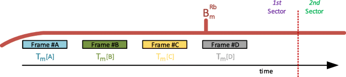
Robust design for the outer precoder


Table 1 collects the different outer precoder designs according to the update and gateway cooperation requirements. The computational burden of the proposed solutions is the same for all the presented designs; they only differ in the kind of channel information employed. For fixed OBBF satellite systems, the robust design provides a set of coefficients for the outer (on-board) precoder. To support a non-fixed BFN design, a more complex payload implementation is required to update the BFN periodically. Conventional space-based beamforming techniques include analog and digital BFN; both kinds of BFN present their particular impairments to set up the BFN coefficients in terms of precision and calibration. OGBF may be a more desirable solution since it avoids the additional complexity on-board the satellite, but it still suffers from calibration issues [34]. Furthermore, OGBF requires the allocation of more feeder link capacity to exchange all the feed signals with the satellite.
5 Results and discussion
We have tested the performance of the proposed two-level precoding scheme in a Monte Carlo simulation for the specifications of a multibeam satellite antenna which uses a feed reflector antenna array with N=155 feeds and Q=100 beams. The radiation pattern is provided by the European Space Agency (ESA) and has been used, among other references, in [22]. We assume FFR, so that the whole bandwidth is available for all beams. The coverage is split into M=10 clusters, each managed by a different gateway, with k=10 beams per cluster. Each gateway exchanges signals with n=30 feeds, so that some feeds are shared by more than one cluster. All the system parameters are collected in Table 2. The sectors for precoding matching purposes are shown in Fig. 4: four sectors per beam are chosen for simplicity and illustration purposes, with users grouped as described in Section 4.3.1. As detailed in that section, more sophisticated sectorization designs can be pursued in accordance with the user scheduling mechanism. The number of users per frame (1, 2, or 3) determines the number of groups per sector for a given user density. Thus, with 24 users per sector and 2 users per frame, 12 groups will be formed per sector.
The two-level precoding scheme has been tested for the different adaptation granularities detailed in Section 4.3.2. Both inner and outer precoders set the required amount of cooperation among gateways. Following Tables 3 and 4, the following cases have been evaluated:
-
1.
Fully adaptive two-level. We assume cooperation among the gateways to share the leakage channels. The outer precoders are fully adaptive, and the cooperative inner precoders are employed.
-
2.
Cooperative sector-based two-level. We assume cooperation among the gateways to share the leakage channels. The outer precoders are sector-based, and cooperative inner precoders are employed.
-
3.
Autonomous sector-based two-level. We assume a distributed solution for the gateways so that they only rely on local instantaneous CSI and second-order statistics of the remaining channel responses. The outer precoders are sector-based, and autonomous inner precoders are employed.
-
4.
Autonomous robust two-level: We assume a distributed solution for the gateways so that they only rely on local instantaneous CSI and second-order statistics of the channel. The outer precoders are fixed (robust design), whereas autonomous inner precoders are employed.
In an ideal cooperation scenario, that is as follows: (i) there are no constraints on the information exchanged by the gateways, (ii) all satellite radiating elements are reachable by all the gateways, and (iii) gateways cooperate to design the precoders, the optimal precoders will have the same performance as the single-gateway scenario. Therefore, the single-gateway implementation sets an upper bound for the performance of the proposed two-level precoder designs. With only one gateway, the two-level precoder is no longer necessary since only intra-cluster interference is present in the system. Thus, the precoder is only formed by the inner precoder and it is designed with (31) by setting the number of clusters to one, M=1. As it could be expected, this precoder is the same as the multicast precoder from [21], since both precoders are designed under the SMSE framework with only one gateway.
The numerical results are presented in Figs. 9, 10, and 11 for different number of users per frame. As performance metric, we use the average frame spectral efficiency across the coverage region which can be obtained as:

Numerical results for 1 user per frame (unicast mode)

Numerical results for 2 users per frame

Numerical results for 3 users per frame
with ηb,m the average spectral efficiency from the bth beam in the mth cluster. For a given frame and realization, with users in set A from the bth beam in the mth cluster, the spectral efficiency is obtained as:
with
where SINR[i] denotes the SINR of ith user. The results are presented versus different signal-to-noise ratio (SNR) values, which are obtained after a calibration process. If \( \mathbf {h}_{b} \in \mathbb {C}^{1\times N}\) denotes the channel vector for a given user within the bth beam in the coverage, then we define the average channel matrix as:
where the expectation is taken with respect to all the users’ locations. With this, the SNR is calibrated as:
with C the transmit beamforming matrix
Among the different two-level strategies, the fully adaptive solution presents the best performance, since it makes use of the instantaneous CSI for the design of both outer and inner precoders, and exploits the cooperation among gateways.
Performance in Figs. 9, 10, and 11 is upper bounded by the single-gateway solution and lower bounded by the autonomous robust scheme.
The performance of a fixed outer precoder is greatly enhanced if a different design is used per sector; even further, no degradation is noticed in such a case when the gateways do not cooperate, and adapt their inner precoders with only real-time local information and statistical global CSI.
The effect of the refreshment rate of the outer precoder can be observed in Fig. 12, which shows the average performance after serving 24 users per beam in 24 consecutive frames, that is, unicast case. All the adaptive schemes combine an outer precoder which remains fixed for the labeled number of frames, with a cooperative inner precoder, as lower bound the performance of the sector-based outer precoder combined with an autonomous inner precoder is also presented. All the curves lie between this lower bound and the performance of the fully adaptive scheme. An interesting conclusion can be drawn if we compare the performance of the lower bound with the adaptive solution with r=24. In both cases, one outer precoder is employed for the whole sector but the adaptive solution requires the cooperation among gateways to share the instantaneous CSI. Thus, in this particular scenario, it may be better to use the sector-based solution since it avoids information exchanges by using the second-order statistics of the channel.

Numerical results for one user per frame (unicast mode) and different outer precoder refreshment periods
In order to evaluate the impact of the multicast, the results for the different two-level designs are presented in Fig. 13 for 1, 2, and 3 users per frame, and a fixed operation point of SNR=20 dB. As expected, the performance degrades with the number of users per frame. It can be also noticed that the single-gateway scenario suffers the most when multicasting comes into play.

Multicast performance for different number of users per frame. SNR =20 dB
A given user will enjoy a spectral efficiency that will depend on a number of factors: its relative location inside the coverage area, the location of the users which are simultaneously served during the same frame, and the precoding scheme. The spectral efficiency empirical probability density function (pdf) is represented for both unicast and multicast (3 users) cases in Figs. 14 and 15, for SNR =20 dB. The upper bound (single gateway with a unique cluster) shows a more compact spectral efficiency distribution, with higher variance in the multicast case. The different precoding versions of the multigateway case achieve a lower average spectral efficiency, as analyzed before, with higher variance: this is the cost of operating with multiple gateways serving clusters which are not isolated from an interference point of view. This higher variance is due to the degraded performance of some beams at the edge of the different clusters, which suffer from the distributed nature of the precoding scheme across the gateways. Nevertheless, the variance of the spectral efficiency shows very low dependence with the number of users per multicast frame, as opposed to the single-gateway case.

Spectral efficiency pdfs for 1 user per frame (unicast mode). SNR =20 dB

Spectral efficiency pdfs for 3 users per frame. SNR =20 dB
6 Conclusions
A combined two-level ground and space precoder has been designed for multibeam satellites with several gateways, able to operate with multicast frames such as those defined in DVB-S2X. The signal-to-leakage and noise ratio criterion has been used to fight inter-cluster interference with the outer precoder, whereas the sum mean-square error drove the design of the inner precoder to mitigate the intra-cluster interference. Flexibility has been achieved with a design which can accommodate the lack of cooperation among the gateways, and tested to operate under different on-board adaptation capabilities. A good scheduling strategy has been also seen to be instrumental to limit the impact of the multicasting and limited adaptation capabilities. Further work could be useful to address the lack of perfect channel information at the gateways, when no real-time accurate CSI is available at the transmitters.
Availability of data and materials
The diagram pattern is provided by the European Space Agency (ESA), and it could be available upon request to ESA.
Notes
For simplicity, we assume that the number of beams per cluster is the same, although in practice could vary. Minor modifications in the notation could serve to describe this more general framework.
In other words, U is n×k whereas S and V are k×k.
blueThe simulations show that the overall SLNR degrades at most by a few dB, whereas the key overall SINR, affected by both intra- and inter-cluster interference, improves by several dB with respect to the solution to (14).
Abbreviations
- HTS:
-
High-throughput satellites
- V/HTS:
-
Very high-throughput satellites
- MUD:
-
Multiuser detection
- GW:
-
Gateway
- FFR:
-
Full frequency reuse
- SLNR:
-
Signal-to-leakage and noise ratio
- OGBF:
-
On-ground beamforming
- SINR:
-
Signal-to-interference plus noise ratio
- GEVD:
-
Generalized eigenvalue decomposition
- OBBF:
-
On-board beamforming
- BFN:
-
Beamforming network
- SMSE:
-
Sum mean-square error
- CSI:
-
Channel state information
- GSA:
-
Geographical Scheduling Algorithm
- ESA:
-
European Space Agency
- SNR:
-
Signal-to-noise ratio
References
D. Minoli, Innovations in Satellite Communications Technology (Wiley, Hoboken, 2015).
B. Devillers, A. Perez-Neira, C. Mosquera, in 2011 IEEE Global Telecommunications Conference - GLOBECOM 2011. Joint Linear Precoding and Beamforming for the Forward Link of Multi-Beam Broadband Satellite Systems (Houston, 2011), pp. 1–6. https://doi.org/10.1109/GLOCOM.2011.6133895.
G. Taricco, in European Wireless 2014; 20th European Wireless Conference. Linear precoding methods for multi-beam broadband satellite systems (Barcelona, 2014), pp. 1–6. https://ieeexplore.ieee.org/document/6843054.
M. A. Vazquez, A. Perez-Neira, D. Christopoulos, S. Chatzinotas, B. Ottersten, P. D. Arapoglou, A. Ginesi, G. Tarocco, Precoding in multibeam satellite communications: present and future challenges. IEEE Wirel. Commun.23(6), 88–95 (2016).
M. Caus, A. I. Perez-Neira, M. Angelone, A. Ginesi, in 2015 IEEE 16th International Workshop on Signal Processing Advances in Wireless Communications (SPAWC). An innovative interference mitigation approach for high throughput satellite systems (Stockholm, 2015), pp. 515–519. https://doi.org/10.1109/SPAWC.2015.7227091.
G. Colavolpe, A. Modenini, A. Piemontese, A. Ugolini, in 2015 IEEE 16th International Workshop on Signal Processing Advances in Wireless Communications (SPAWC). Multiuser detection in multibeam satellite systems: theoretical analysis and practical schemes, (2015), pp. 525–529. https://doi.org/10.1109/SPAWC.2015.7227093.
R. De Gaudenzi, N. Alagha, M. Angelone, G. Gallinaro, Exploiting code division multiplexing with decentralized multiuser detection in the satellite multibeam forward link. Int. J. Satell. Commun. Netw.36(3), 239–276 (2018). https://doi.org/10.1002/sat.1215. https://onlinelibrary.wiley.com/doi/pdf/10.1002/sat.1215.
A. Ugolini, G. Colavolpe, A. Vanelli-Coralli, in 2017 International Symposium on Wireless Communication Systems (ISWCS). A system level approach to the application of multiuser detection in multibeam satellite systems (Bologna, 2017), pp. 66–71. https://doi.org/10.1109/ISWCS.2017.8108163.
T. Ramírez, C. Mosquera, M. Caus, A. Pastore, M. Navarro, N. Noels, in 2018 9th Advanced Satellite Multimedia Systems Conference and the 15th Signal Processing for Space Communications Workshop (ASMS/SPSC). Message-Splitting for Interference Cancellation in Multibeam Satellite Systems (Berlin, 2018), pp. 1–7. https://doi.org/10.1109/ASMS-SPSC.2018.8510733.
D. Christopoulos, P. -D. Arapoglou, S. Chatzinotas, in 31st AIAA International Communications Satellite Systems Conference(ICSSC). Linear precoding in multibeam satcoms: practical constraints (American Institute of Aeronautics and AstronauticsFlorence, 2013). https://doi.org/10.2514/6.2013-5716.
D. Christopoulos, S. Chatzinotas, B. Ottersten, in 2014 7th Advanced Satellite Multimedia Systems Conference and the 13th Signal Processing for Space Communications Workshop (ASMS/SPSC). Frame based precoding in satellite communications: a multicast approach, (2014), pp. 293–299. https://doi.org/10.1109/ASMS-SPSC.2014.6934558.
ETSI EN 302 307-2 V1.1.1 (2014-10), Digital video broadcasting (DVB); second generation system for broadcasting, interactive services, news gathering and other broadband satellite applications. Part 2 - S2 Extensions (DVB-S2X).
DVB Blue Book A83-2, Second generation system for broadcasting, interactive services, news gathering and other broadband satellite applications. Part 2 - S2 Extensions (DVB-S2X).
A. Guidotti, A. Vanelli-Coralli, Clustering strategies for multicast precoding in multibeam satellite systems. Int. J. Satell. Commun. Netw. (2019). https://doi.org/10.1002/sat.1312. https://onlinelibrary.wiley.com/doi/pdf/10.1002/sat.1312.
A. Guidotti, A. Vanelli-Coralli, in 9th Advanced Satellite Multimedia Systems Conference (ASMS) and 15th Signal Processing for Space Communications Workshop (SPSC). Geographical scheduling for multicast precoding in multi-beam satellite systems (Berlin, 2018). http://arxiv.org/abs/1804.06614.
E. Lagunas, S. Andrenacci, S. Chatzinotas, B. Ottersten, in 9th Advanced Satellite Multimedia Systems Conference (ASMS) and 15th Signal Processing for Space Communications Workshop (SPSC). Cross-layer forward packet scheduling for emerging precoded broadband multibeam satellite system (Berlin, 2018). http://arxiv.org/abs/1804.06614.
A. Kyrgiazos, B. Evans, P. Thompson, N. Jeannin, in 2012 6th Advanced Satellite Multimedia Systems Conference (ASMS) and 12th Signal Processing for Space Communications Workshop (SPSC). Gateway diversity scheme for a future broadband satellite system, (2012), pp. 363–370. https://doi.org/10.1109/ASMS-SPSC.2012.6333101.
D. Mignolo, P. Angeletti, E. Re, A. B. Alamanac, M. Harverson, A. Ginesi, in 17th Ka and Broadband Communications Conference. Approaching terabit/s satellite: a system analysis (Palermo, 2011), pp. 3–5. https://www.researchgate.net/publication/236334565_Approaching_Terabits_satellite_capacity_A_system_analysis.
A. Gharanjik, B. S. M. R. Rao, P. Arapoglou, B. Ottersten, in 2013 IEEE 24th Annual International Symposium on Personal, Indoor, and Mobile Radio Communications (PIMRC). Large scale transmit diversity in q/v band feeder link with multiple gateways, (2013), pp. 766–770. https://doi.org/10.1109/PIMRC.2013.6666239.
A. Gharanjik, K. Liolis, M. R. B. Shankar, B. Ottersten, in 2014 IEEE Global Conference on Signal and Information Processing (GlobalSIP). Spatial multiplexing in optical feeder links for high throughput satellites, (2014), pp. 1112–1116. https://doi.org/10.1109/GlobalSIP.2014.7032294.
D. Christopoulos, H. Pennanen, S. Chatzinotas, B. Ottersten, in 2016 8th Advanced Satellite Multimedia Systems Conference and the 14th Signal Processing for Space Communications Workshop (ASMS/SPSC). Multicast multigroup precoding for frame-based multi-gateway satellite communications, (2016), pp. 1–6. https://doi.org/10.1109/ASMS-SPSC.2016.7601466.
C. Mosquera, R. López-Valcarce, T. Ramírez, V. Joroughi, Distributed precoding systems in multi-gateway multibeam satellites: regularization and coarse beamforming. IEEE Trans. Wirel. Commun.17(10), 6389–6403 (2018). https://doi.org/10.1109/TWC.2018.2859410.
T. Ramirez, C. Mosquera, R. Lopez-Valcarce, in WSA 2018; 22nd International ITG Workshop on Smart Antennas. Two-level precoding for high throughput satellites with non-cooperative gateways, (2018), pp. 1–6.
D. Kim, G. Lee, Y. Sung, Two-stage beamformer design for massive MIMO downlink by trace quotient formulation. IEEE Trans. Commun.63(6), 2200–2211 (2015). https://doi.org/10.1109/TCOMM.2015.2429646.
A. Liu, V. Lau, Hierarchical interference mitigation for massive MIMO cellular networks. IEEE Trans. Signal Process.62(18), 4786–4797 (2014). https://doi.org/10.1109/TSP.2014.2340814.
J. Chen, V. K. N. Lau, Two-tier precoding for FDD multi-cell massive MIMO time-varying interference networks. IEEE J. Sel. Areas Commun.32(6), 1230–1238 (2014). https://doi.org/10.1109/JSAC.2014.2328391.
A. Adhikary, J. Nam, J. Y. Ahn, G. Caire, Joint spatial division and multiplexing – the large-scale array regime. IEEE Trans. Inf. Theory. 59(10), 6441–6463 (2013). https://doi.org/10.1109/TIT.2013.2269476.
J. Nam, A. Adhikary, J. Y. Ahn, G. Caire, Joint spatial division and multiplexing: opportunistic beamforming, user grouping and simplified downlink scheduling. IEEE J. Sel. Top. Signal Process.8(5), 876–890 (2014). https://doi.org/10.1109/JSTSP.2014.2313808.
A. Alkhateeb, G. Leus, R. W. Heath, Multi-layer precoding: a potential solution for full-dimensional massive MIMO systems. IEEE Trans. Wirel. Commun.16(9), 5810–5824 (2017). https://doi.org/10.1109/TWC.2017.2716362.
M. Sadek, A. Tarighat, A. H. Sayed, Active antenna selection in multiuser MIMO communications. IEEE Trans. Wirel. Commun.55(4), 1498–1510 (2007). https://doi.org/10.1109/TSP.2006.888893.
W. W. L. Ho, T. Q. S. Quek, S. Sun, R. W. Heath, Decentralized precoding for multicell mimo downlink. IEEE Trans. Wirel. Commun.10(6), 1798–1809 (2011). https://doi.org/10.1109/TWC.2011.040511.100519.
S. He, C. Qi, Y. Huang, Q. Hou, A. Nallanathan, Two-level transmission scheme for cache-enabled fog radio access networks. IEEE Trans. Commun.67(1), 445–456 (2019).
B. N. Parlett, The Symmetric Eigenvalue Problem (Prentice-Hall, Inc., Upper Saddle River, 1998).
G. Gallinaro, S. Cioni, F. Vanin, O. Vidal, G. Huggins, M. Gross, S. Andrenacci, S. Chatzinotas, E. Tirro, in 2016 8th Advanced Satellite Multimedia Systems Conference and the 14th Signal Processing for Space Communications Workshop (ASMS/SPSC). Future ground beamforming, (2016). https://doi.org/10.1109/ASMS-SPSC.2016.7601548.
Acknowledgements
Not applicable.
Funding
This work was funded by the Xunta de Galicia (Secretaria Xeral de Universidades) under a predoctoral scholarship (cofunded by the European Social Fund), and it was partially funded by the Agencia Estatal de Investigación (Spain) and the European Regional Development Fund (ERDF) under projects MYRADA (TEC2016-75103-C2-2-R) and WINTER (TEC2016-76409-C2-2-R).
Author information
Authors and Affiliations
Contributions
Authors’ contributions
Tomas Ramírez (TR), Carlos Mosquera (CM), and Roberto López-Valcarce (RL) developed the analytical derivations. TR designed and run the simulations. TR, CM, and RL wrote the manuscript. TR, CM, and RV proofread the manuscript. All authors read and approved the final manuscript.
Authors’ information
The authors are with the atlanTTic research center, University of Vigo, 36310, Galicia, Spain.
Corresponding author
Ethics declarations
Competing interests
The authors declare that they have no competing interests.
Additional information
Publisher’s Note
Springer Nature remains neutral with regard to jurisdictional claims in published maps and institutional affiliations.
Rights and permissions
Open Access This article is licensed under a Creative Commons Attribution 4.0 International License, which permits use, sharing, adaptation, distribution and reproduction in any medium or format, as long as you give appropriate credit to the original author(s) and the source, provide a link to the Creative Commons licence, and indicate if changes were made. The images or other third party material in this article are included in the article’s Creative Commons licence, unless indicated otherwise in a credit line to the material. If material is not included in the article’s Creative Commons licence and your intended use is not permitted by statutory regulation or exceeds the permitted use, you will need to obtain permission directly from the copyright holder. To view a copy of this licence, visit http://creativecommons.org/licenses/by/4.0/.
About this article

Cite this article
Ramírez, T., Mosquera, C. & López-Valcarce, R. Two-level frame precoding with non-cooperative gateways. J Wireless Com Network 2020, 151 (2020). https://doi.org/10.1186/s13638-020-01757-7
Received:
Accepted:
Published:
DOI: https://doi.org/10.1186/s13638-020-01757-7