- Research
- Open access
- Published:
Small cell backhaul: challenges and prospective solutions
EURASIP Journal on Wireless Communications and Networking volume 2015, Article number: 206 (2015)
Abstract
Operators are currently considering the deployment of small cells to complement their macrocellular networks and increase their coverage and capacity. However, in order to roll-out a large number of small cells and allow anytime, anywhere wireless broadband connectivity through wireless technologies, operators must still face the challenge of backhauling the traffic from the small cells to the core network in a cost-effective manner. In this paper, backhaul challenges for small cell base stations (BSs) are discussed, and potential wired and wireless solutions together with their benefits and drawbacks are presented. The use of large scale antennas systems and free-space optics is also discussed. Moreover, a wireless backhaul planning tool targeted at finding the most cost-effective backhaul solution using a mixture of wireless technologies is presented. Simulation results confirm that the optimum backhaul solution is a combination of various options, which can overcome inherent scenario constraints while providing a cost-effective performance.
1 Introduction
Long Term Evolution (LTE) can significantly boost network capacity compared to high-speed packet access (HSPA), using more antennas and bandwidth as well as providing a higher spectral efficiency through opportunistic scheduling. However, this network capacity improvement will not be sufficient to meet the future user equipment (UE) traffic demands, which have been forecasted to grow exponentially over the coming years [1]. As a result, vendors and operators are looking for new approaches to increase network capacity.
Among the considered approaches, network densification has been heralded as the most promising solution to meet the predicted traffic demands, since it has the potential to increase network capacity with the number of deployed cells through spatial reuse [2]. However, because of the limited rooftop space, the densification of today’s macrocellular networks comprised of high transmit power base stations (BSs) is only possible up to a certain extent, resulting in minimum inter-site distances (ISDs) of around 250 m. Therefore, further network densification requires new BSs with a smaller form factor, the so-called small cell BSs [3], which offer more flexible deployment opportunities.
Small cell BSs are low-cost low-power BSs, which have similar functionalities as macrocell BSs but with a much smaller form factor. They are mainly deployed to provide localised coverage and capacity at households or in hot-spot areas such as city centres and transport hubs. Small cell BSs use the same interfaces (S1, X2, Iub, Iuh) as macrocell BSs and thus can be easily integrated, coexist and cooperate with the existing macrocellular networks [3]. However, in contrast to existing macrocell BSs, which often can only be deployed within a few hundred metres of their ideal location due to site acquisition issues, small cell BSs can be placed much closer to their ideal positions given their reduced size. As a result, they can be deployed in strategic locations to leverage current infrastructure, while taking UE densities, traffic demands and radio propagation conditions into account [4]. For example, small cell BSs can be deployed either
-
outdoors on street furniture (e.g. lamp posts, bus shelters and buildings sides) to provide service to the surrounding streets and the lower floors of buildings; or
-
indoors in public spaces and highly demanding areas as well as in the middle floors of high buildings to provide service to its middle and high floors and those of neighbouring buildings.
A blanket of small cell BSs can also be used to cover hot-spot areas that are beyond the coverage/capacity of a single small cell BS [3].
Due to their deployment flexibility and lower maintenance costs and because they have been shown to significantly improve network capacity, operators are already widely adopting small cells [5]. According to the Small Cell Forum, around 67 % of the operators have already deployed indoor small cells (i.e., femtocells) and it is predicted that the number of deployed femtocells will considerably increase from 4.3 million to 36.8 million by 2015. AT&T has also announced the deployment of more than 40,000 outdoor small cells (i.e., metrocells) by the end of 2015 [6]. However, despite their benefits, in order to roll-out a large number of small cells, operators must still face the challenge of backhauling the network traffic from small cell BSs to the core network. Indeed, a recent survey [6] showed that around 56 % of operators consider backhaul as one of the greatest challenges in future cellular communications. This is mainly because most of small cell BSs do not always have access to wired backhaul connectivity and because today the cost of the wireless backhaul equipment exceeds the cost of the small cell BS itself.
In this paper, we discuss challenges and prospective solutions to backhaul. In more detail, in Section 2, the concept of backhaul and the main differences between macrocell and small cell backhauls are introduced. In Section 3, the most important challenges in small cell backhaul are discussed. In Section 4 and Section 6, current and more futuristic solutions to small cell backhaul are presented, respectively. In Section 5, a case of study that assesses the performance of current wireless small cell backhaul solutions is shown. In Section 7, the conclusions are drawn.
2 Small cell backhaul
In this section, the concept of the backhaul network and its principal components are introduced, together with the main differences between macrocell and small cell backhauls.
2.1 Backhaul architecture
The term backhaul network refers to the intermediate network that includes the links between the radio access network and the core network. The backhaul network thus starts at the cell site and ends up in the core network as shown in Fig. 1. In the following and for the sake of clarity, we describe the principal components of a backhaul network as well as some related concepts.
-
Macrocell refers to the coverage area provided by a high transmit power BS. The macrocell radius is around 0.25–10 km with antenna heights over 25 metres.
Fig. 1 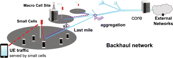
Backhaul network architecture [3]
-
Small cell refers to the coverage area provided by a low transmit power BS. The small cell radius is around 10–200 m with antenna heights under 25 metres.
-
Point of Presence (PoP) refers to a central access point where the traffic from different cells is aggregated. Rooftop macrocell BSs can act as PoPs to underlay small cell BSs, with a PoP density of around 9 sites per square kilometre assuming an ISD of 500 m.
-
Small cell (aggregation) gateway can be used to provide connectivity for a number of small cells to the backhaul network, acting as an aggregation point and a PoP. The small cell aggregation gateway improves scalability, reduces the number of required S1 interfaces and provides control and user plane functionalities to lower the signalling load on the core network components [3]. However, small cell connectivity to the small cell aggregation gateway may not always be available.
-
Line-of-Sight (LOS) refers to a scenario where the small cell BS accesses the PoP via a direct non-blocked link, while Non-Line-of-Sight (NLOS) refers to a situation where the radio transmission across the direct path between the small cell BS and the PoP is obstructed, usually by a physical object. In case of NLOS, the main communication occurs through reflection, diffraction and/or diffusion.
-
Point-to-Point (PtP) refers to a one-to-one communication between the PoP and a small cell BS.
-
Point-to-Multipoint (PtMP) refers to a one-to-many communication between the PoP and multiple small cell BSs. PtMP communications are very much related to NLOS conditions and low-frequency bands (e.g., sub-6 GHz) and are able to overcome signal obstructions. In this case, the PoP acts as a unique data sink and can be equipped with either an omnidirectional antenna or a number of directional antennas pointing in different directions, e.g., antenna arrays with static beams, large scale antenna systems (LSAS) [7]. The latter solution with directional antennas enables the use of higher frequency bands and thus larger bandwidths due to the higher antenna gains, provided that LOS exists. However, the use of an omnidirectional antenna at the PoP eases the built-in installation and coordination requirements imposed due to beamforming.

2.2 Macro and small cell backhaul differences
Since small cell BSs are deployed in larger numbers and should incur a much lower cost than macrocell BSs, the cost per small cell backhaul connection has to be significantly lower than that per macrocell backhaul connection. As a result, the small cell backhaul has to be a packed version of the macrocell backhaul. In order to achieve this objective, the small cell backhaul should be properly dimensioned and quality of service (QoS) could be relatively relaxed in terms of backhaul capacity in coverage scenarios (e.g., coverage expansion) and backhaul availability in capacity scenarios (e.g., hot spots) [3].
While dimensioning small cells backhauls, it is important to consider that small cell BSs may have a higher peak and busy hour throughput than macrocell BSs, which emphasises the need for high capacity backhaul links to meet the expected small cell QoS requirements at busy time periods. Small cell BS may also generate in average less but burstier traffic than macrocell BSs, due to its lower number of connected UEs, and thus, traffic aggregation may be essential to improve the efficiency and reduce the cost of small cell backhaul. Aggregating backhaul traffic through a linear backhaul topology may be the easiest solution to realise. However, this topology may result in single points of failure, which encourages operators to consider more resilient but expensive backhaul topologies, e.g., star and mesh.
From an implementation perspective, providing small cell backhaul at street levels is more challenging and expensive than providing macrocell backhauling at rooftops. This is because it is difficult to reach street levels using inexpensive LOS links. Deploying backhauling at street levels also requires backhaul equipment which has to be compact and secure to avoid accidental damages and tampering as well as to ease the deployment.
3 Technical challenges for small cell backhauling
In this section, a survey of the main technical challenges that vendors and operators need to address to provide a cost-effective small cell backhaul is presented.
-
1.
Physical Design/Hardware Architecture
Different types of small cell BSs may require different types of backhaul designs and architectures since they can be deployed at very different locations1. Therefore, the physical design and architecture is a critical difference between various backhaul solutions, which impacts the possibility of different deployment locations and the associated backhaul costs. Three physical structures are generally considered, which are referred to as full separation, moderate separation and full integration. In the first case, the small cell and backhaul units are two entirely separated structures with separate enclosures, while in the second case, they are placed within a single enclosure which better protects the interconnections between the small cell and backhaul units against weather, accidental damages and tampering. As an alternative, the backhaul unit may be completely integrated into the small cell BS. This reduces the size and eases the deployment of the solution. In all cases, electrical surge protection, secure mounting and safety cable connector locks have to be used to minimise the probability of physical contact with the general public [3].
-
2.
Coverage
Providing a high quality connectivity between the small cell BSs and the core network is a challenge, and it may require large planning efforts since various existing backhaul solutions encounter distinct difficulties. The backhaul coverage of a wired solution is defined by its deployment and connecting sockets, while that of a wireless solution is defined by the coverage of the PoP, i.e., the area where small cell BSs can connect with such PoP. The larger the PoP backhaul coverage, the less PoPs are needed but the higher the probability of NLOS.
-
In terms of wired solutions, due to the high costs associated with the installation of new wired connections, the existing infrastructure may highly dominate the deployment of small cell BSs and PoPs. For example, small cell BSs and PoPs can be deployed to leverage current fibre infrastructure. However, this may result in sub-optimal small cell BS and PoP placement from an off-loading or radio propagation perspective.
-
The wireless solutions have to consider whether LOS or NLOS links and PtP or PtMP communications are available/used between the small cell BSs and the PoPs. Considering the provision of wireless backhaul coverage through LOS wireless links, the main challenge is the availability of a clear link between the small cell BS and the PoP. Figure 2 shows the probability of LOS versus distance in urban environments based on the WINNER II channel model, which drops to less than 0.5 for distances beyond 75 m. Therefore, in co-channel deployments, where small cells are not deployed close to macrosites to avoid interference, LOS wireless backhaul may not be seen as a feasible solution in a large number of cases. Moreover, the wireless backhaul coverage is also impacted by atmospheric attenuation. Certain frequencies suffer from higher attenuation than others, due to the mechanical resonance of gas molecules [8, 9]. Since atmospheric loss has its most significant impact on links of over 1 km, this may not be a bottleneck to small cells if they are located within distances of a hundred metres from the PoP. As a result, LOS links for small cell BSs may not always be feasible, only at short distances, and NLOS links may have to be used in dense urban areas, as they enable more small cell deployment locations. PtMP communications may also facilitate backhaul deployment with respect to PtP communications since the PoP covers a wider area and does not require antenna alignment. However, NLOS and PtMP solutions both suffer from low capacity because of the constrained spectrum availability at lower frequency bands, usually associated to them, and due to the multiplexing of several small cell flows at the PoP.
Fig. 2 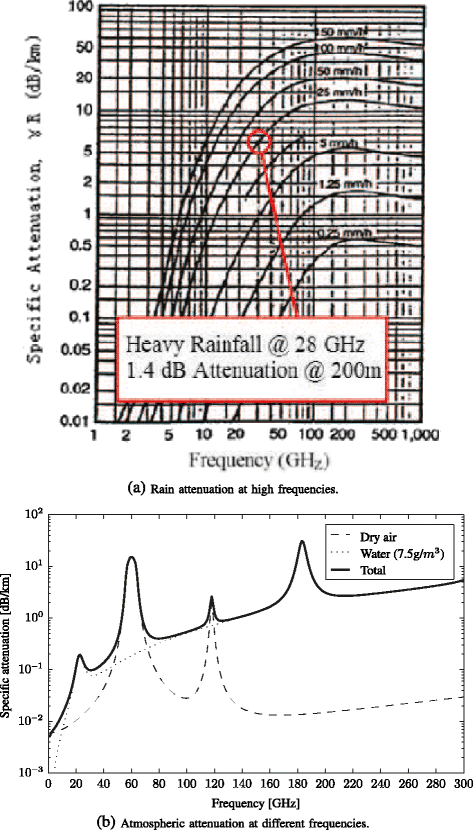
Probability of LOS link versus distance
-
-
3.
Capacity
The backhaul capacity must not constrain the small cell capacity [3]. Thus, the backhaul capacity should be able to support the busy hour traffic and have enough margin to cover its future growth and statistical variation [10]. In wireless backhaul, the available bandwidth, share of radio resources and modulation scheme (and hence SINR) impact the backhaul capacity. However, dimensioning the backhaul capacity for the worst case scenario will result in over-provisioning and more expensive solutions. This is because providing high capacity may require the deployment of more PoPs and the use of more sophisticated technologies. As a common indicator for dimensioning, the busy hour traffic can be assessed with regard to two different loading conditions, known as busy times and quiet times, resulting in two traffic indicators, the quiet time peak cell throughput and the busy time mean cell throughput, respectively [4]. During quiet times, it is most likely that a single UE has access to the whole spectrum. If the signal quality of this UE is high, the cell throughput reaches its peak. This condition is referred to as the quiet time peak cell throughput. In contrast, during busy times, many UEs access the spectral resources of the cell and experience different signal qualities, and the busy time mean cell throughput can be computed averaging the throughputs of all UEs during the busy hour. Dimensioning the backhaul network for the busy time mean cell throughput will result in a reduced cost, since it is always lower than the quiet time peak cell throughput, but may prevent operators to exploit the full benefit of small cells. The minimum target today in order to backhaul LTE small cells is around 50 Mbps, and 150 Mbps or higher capacities are required to support peak data rates [10]. These numbers are expected to grow as multiple radio access technologies and additional spectrum become available for small cells.
-
4.
Synchronisation
Frequency and time synchronisations are essential to guarantee that transmitted signals use their specific allocated channels and comply with license regulations and system requirements. Time synchronisation is also particularly critical in time division duplexing (TDD) systems to avoid interference between the downlink and uplink of adjacent cells and enable enhanced features such as enhanced inter-cell interference coordination (eICIC) and coordinated multipoint (CoMP) transmission/reception. The Global Navigation Satellite System (GNSS) can be used to provide accurate frequency and time synchronisation outdoors, but it may not work well indoors or outdoors where there is limited or no view of the sky [3]. In this case, achieving frequency and time synchronisation may require the support of backhaul based techniques, which rely on a well performing backhaul solution. The development of new synchronisation solutions such as local deployment of a synchronisation server, over-the-air synchronisation techniques or hybrid solutions can ease the requirements on the backhaul for synchronisation purposes [11].
-
5.
Cost
The cost factor is one of the most important aspects to assess the backhaul solution. Backhaul contributes to a significant portion of the overall small cell cost, and thus, backhaul cost reduction becomes a priority, noting that operators aim to bring down the small cell backhaul cost to about 10 % of the macrocell backhaul cost.
Backhaul total cost of ownership (TCO) can be generally classified as capital and operation expenditures, referred to as Capex and Opex, respectively. The Capex and Opex costs can be further categorised into initial and ongoing (annual) costs. For Capex, the initial costs comprise the Ethernet switching and equipment expenses such as antennas and waveguides as well as spares, while the annual costs include backhaul upgrades and expansions. For Opex, the initial expenses are due to design, installation and commissioning as well as spectrum license and site development costs where the latter includes the site permissions, upgrades and analysis. The contributors to Capex and Opex costs vary depending on exploiting wired or wireless backhaul solutions. For wireless backhaul cost, the main contributors are cell site router, power connection cost per site, radio frequency (RF) engineering and annual maintenance and management costs per link. For wired solutions, buried cable cost per site, digital subscriber line (DSL) outdoor modem and fibre cost per metre incur further costs to the overall backhaul cost. The Ethernet leasing also has to deal with monthly bandwidth charges.
For wireless solutions, the backhaul Capex cost can be highly impacted by the network topology, i.e., PtP and PtMP [12]. Considering dense deployments and reducing the cell radius from 600 to 400 and 300 m, the backhaul Capex cost may increase from $6.752K to $14.888K and $27K for PtP solutions and from $2.964K to $5.352K and $9.704K for PtMP solutions, respectively. Moreover, the backhaul Opex comprises of an initial high cost for the purchase and integration of the new microwave radios into the network, e.g., $6K–15K for each PtP link. It is worth to mention that for PtMP solutions, the increase in Capex expenses due to densification is accompanied with reduction in Opex costs due to smaller footprints in dense deployments. As an example and according to [13], the total Capex and Opex costs for small cell deployments in urban London over a period of 10 years is around $141M and $1429M, respectively. This clearly shows the burden that backhaul represents and the necessity to design more cost-effective backhaul solutions.
In order to put the backhaul into perspective, the overall network deployment cost analysis in [14] can be considered, which takes into account infrastructure cost, capacity cost and equipment cost. The authors model the whole network as a superposition of multiple layers including BS layer, UE layer and backhaul layer and then discuss the main contributors to the mentioned cost types, including backhaul. They use the term equipment cost to denote the cost of a device being deployed (e.g., cell BS, backhaul node), noting that service providers do not incur any equipment cost. The term capacity cost refers to the cost involved in connecting two adjacent layers subject to meeting the required capacity and is modelled as A i,i+1×f(r) where A i,i+1 is the cost per kilometre and \(\textit {f}(r) = \textit {r}^{\beta _{i,i+1}}\phantom {\dot {i}\!}\) is a function which indicates the cost increase based on the distance r between the points of the layers to be connected and the cost increases exponentially with β i,i+1. The term infrastructure cost refers to the cost of physically connecting two points of the two layers and is similarly modelled as B i,i+1×g(r) where B i,i+1 and g(r) are analogous to A i,i+1 and f(r), respectively. Having discussed the cost types, the authors further define the overall network cost as \(\textit {C}_{\text {tot}} = \sum \lambda _{i}(\textit {C}_{i} + \textit {C}_{\phi _{i}})\) where C i is the equipment cost at the i th network layer, \(\textit {C}_{\phi _{i}}\) is the cost associated with the i th network layer and λ i denotes the node density in each layer, i.e., BSs, UEs and backhaul nodes on the i th network layer. Optimisation of the backhaul solution including the optimised number of backhaul nodes is necessary and should be conducted subject to minimising the Capex cost (referred by authors as deployment cost) as well as meeting the UEs’ required QoS.
Tables 1 and 2 summarise the values for different cost types and the corresponding exponents.
Exploiting mesh network topology along with advanced adaptive coding and modulation (ACM) schemes and reducing the antenna size are among techniques that can further reduce the backhaul cost. Software controlled scalability is also effective in decreasing the backhaul costs. Employing advanced processing techniques at small cells which will be discussed in Section 6.3 can also potentially reduce the Opex cost. More detailed backhaul cost analysis is available in [12, 13, 15].

4 Solutions for small cell backhaul
As discussed earlier, there are various solutions for the implementation of small cell backhaul, mainly belonging to the two categories of wired and wireless solutions. This has to be expressed that an ideal backhaul solution is referred to as one that provides a very high throughput of around 10 Gbps subject to a latency of less than 2.5 μs. Table 3 summarizes the associated throughput and latency of various backhaul solutions.
4.1 Wired backhaul from small cell BS to PoP
The wired backhaul takes advantage of its high availability and capacity. Digital subscriber line (DSL) and fibre form the main wired backhaul solutions.
-
1.
DSL
The widely deployed telephone infrastructure based on copper twisted pair is used in the DSL case, which typically ranges from 256 kbps to 40 Mbps in the downlink [3]. The main downsides of residential DSL are the asymmetric bandwidth, which makes DSL face distance limited bandwidth issues as well as the asymmetric bandwidth constraints, and the cross talk, which is the interference between the copper lines in the same cable and is the main sources of data rate degradation in DSL. Information about different types of cross talk can be found at [16].
The standard very high speed digital subscriber line 2 (VDSL2) is an enhancement of DSL and is able to offer around 40 and 30 Mbps at distances of 400 and 1000 m, respectively. In addition, vectoring and pair bonding are techniques that can be used in VDSL2 to deal with cross talk and further boost its performance. Vectoring estimates and cancels the interference continuously and allows all the copper lines to gain higher capacity [17], while pair bonding increases the bandwidth or extends its reach by inverse multiplexing, i.e., multiple DSL lines are bonded to offer a summed data rate [17]. VDSL2 with vectoring can achieve downlink speeds of 100 and 40 Mbps at distances of up to 400 and 1000 m, respectively. Bonding has been demonstrated to boost the bandwidth with the number of copper lines. The two-pair and eight-pair bonding VDSL2 without exploiting any vectoring can approach data rates of nearly 80 and 250 Mbps, respectively[18]. Exploiting both vectoring and eight-pair bonding techniques with VDSL2, data rates of 350 Mbps for downlink and 70 Mbps for uplink at a distance of around 1000 m can be achieved. Full study on performance evaluation of VDSL2 technology is available at [19–21].
The symmetric high-speed DSL (G.SHDSL) technology also uses multipair bonding. However, unlike asymmetric DSL, it can offer symmetrical performance of 22 Mbps over long distances and has been mainly used in business applications which require higher speed in both downlink/uplink directions. Impulse noise protection (INP) with forward error correction (FEC) is another technique to help VDSL2 against burst errors [17, 22].
Going further, XG-Fast is a new technology, which is able to achieve a data rate of 10 Gbps through copper lines [23], and its very short length loops makes it particularly suitable for residential networks. XG-Fast is a single user technology (no cross talk) and thus benefits from signal coordination at both transmitter and receiver sides and can exploit more efficient equalisation techniques. In addition to the discussed techniques, XG-Fast also benefits from transmitter controlled AMC, which can further boost the data rate [23]. With a frequency range of 106 MHz, XG-Fast can achieve data rates of 500 Mbps over distances of 100 m. Using a higher frequency range of 350 MHz, XG-Fast can enhance the data rate to 1 Gbps symmetrical over distances of 70 m. By bonding two pairs of lines over a distance of 30 m and a frequency range of 500 MHz, the 10 Gbps data rate can be gained.
-
2.
Fibre
A fibre link is more predictable than a copper one and can provide significantly higher ranges of up to 100 km. It also can considerably enhance the backhaul capacity with throughputs of up to 400 Gbps, while maintaining the connection latency low [3, 5]. The Ethernet standards determine the properties of fibre transceivers. Lighting several fibre pairs can considerably boost the backhaul capacity. Optical transport systems with bidirectional capacity of up to 8.8 Tbps are already available.
Gigabit passive optical network (GPON) is a PtMP technology, which uses passive splitters within the fibre network and allows one single feeding optical fibre to provide service to multiple network nodes. GPON can take advantage of a large data packet to increase bandwidth and spectral efficiency, offering data rates of 2.488 Gbps for the downlink and 1.244 Gbps for the uplink [24]. In case of bandwidth shortage, PON engineering techniques can be designated to change the bandwidth share in order to offer more bandwidth to high demand nodes. For example, wavelength division multiplexing (WDM) is used in GPON to allow the use of a single optical fibre for both uplink and downlink. WDM PON utilises specific wavelengths for specific optical network components or links, while they all use the same physical infrastructure. The detailed structure of GPON technology is discussed in [25]. Going further, X-GPON or 10-GPON as the next generation of GPON can achieve data rates of 10 and 2.48 Gbps for downlink and uplink, respectively. X-GPON benefits from long distance coverage of up to 10 km due to its higher optical power, as well as a significant increase in number of subscribers by offering the split ratio of 1:128 in comparison to 1:64 in GPON. To deliver the compatible co-existence of both GPON and X-GPON technologies, WDM and WDMA technologies are used for downlink and uplink, respectively. In [26], a converged optical architecture for backhaul using WDM PON is presented. The proposed technique dynamically re-allocates the downlink wavelength for the purpose of load balancing, which mainly benefits from guiding the traffic towards frequencies that deal with less or no congestion.
Fibre based networks are usually implemented using two infrastructures, fibre to the home (FTTH) and fibre to the node (FTTN). FTTH takes advantage of a potential unlimited spectrum, whereas FTTN uses VDSL2 technology in the last 1000 m to reutilise the operator’s available copper technology. This avoids the need for trenching fibre to every home, thus reducing cost, while offering a competitive quality of service. XG-Fast technology can be considered to replace the VDSL2 in the FTTN scheme.
In order to leverage the good performance of fibre, in [27], the authors suggest that small cell BSs should be deployed at locations with existing fibre links and they develop a computationally efficient heuristic algorithm to select the most appropriate small cell locations out of all potential fibre-provided candidate sites. However, despite of its advantages, fibre may not always be available or the associated installation and/or operating costs may be much higher than that of DSL. It is also important to note that considering the need to keep up with the increasing traffic demands, installing wired backhaul in all new small cell sites may not be cost-effective, if possible at all, and wireless backhaul may be the only possible solution in some cases.
4.2 Wireless backhaul from small cell BS to PoP
The wireless backhaul benefits from its significantly increased flexibility regarding small cell locations. The most common wireless backhaul solutions include sub-6 GHz PtMP, microwave PtMP, microwave PtP and millimetre wave PtP. The major criteria in assessment of the viability of a wireless backhaul solution includes capacity dimensioning, as discussed before, as well as LOS availability, network topology and carrier frequency.
Since each small cell BS in a dense urban scenario will meet different environmental conditions, the appropriate small cell wireless backhaul solution will be comprised of a mix of backhaul options, which exploits the different trade-offs among LOS versus NLOS, PtP versus PtMP and low frequency versus high frequency. These trade-offs are discussed in the following:
-
1.
LOS Availability
NLOS backhaul solution is an alternative to the traditional LOS backhaul solution in macrocellular environments for cases in which there is no direct path between the small cell BS and the PoP. NLOS solutions provide a wider coverage area in comparison to LOS solutions in urban environments, thus easing the deployment procedure and antenna alignment. In order to benefit from propagation conditions, NLOS wireless backhaul is designated for carrier frequencies below 6 GHz [4] and is usually OFDM based to mitigate the impact of multipath fading with channel bandwidth of 10 to 20 MHz.
NLOS solutions are highly linked to PtMP topologies, using a hub module as the PoP to connect the small cell BSs to the core network. The hub module antennas are typically deployed at rooftops to take advantage of better propagation environment, which reduces the path loss and increases the range between the small cell BSs and the hub module. In order to increase antenna gain and reduce the interference, the hub module may use an array of antennas with advanced beamforming techniques to improve its performance compared to the use of an omnidirectional antenna. Interference issues are more severe when NLOS wireless backhaul is used in unlicensed bands due to the contention for the channel among UEs of different technologies and operators. NLOS solutions also suffer from low capacity compared to LOS solutions due to the limited economically available spectrum at low-frequency bands.
-
2.
Network Topology
PtP backhaul is highly linked to the availability of LOS link and depends on high gain narrow beam antennas. However, in case of absence of such link to the PoP, the two alternative PtP solutions are hop and daisy chain solutions. In hop solutions, the small cell BS is linked to the PoP via a set of intermediate PtP LOS connections, while in the daisy chain solutions, the small cell BS connects to the PoP through secondary locations co-located with other small cell BSs. Thus, links of close proximity to the PoP have higher capacity requirements in order to accommodate the traffic demand from several small cell BSs.
PtMP backhaul has a larger flexibility than PtP backhaul due to the resulting wider coverage area of the PoP, as discussed before. Moreover, it can leverage multiplexing and let the backhaul capacity be automatically and dynamically shared among multiple small cell BSs, allowing operators to connect new small cell BSs to existing PoPs in an on-demand manner as hot spots appear.
A LOS PtMP backhaul solution where the PoP is equipped with directional antennas pointing in different directions is well suited for higher frequency bands due to the larger antenna gains, thus allowing to exploit larger bandwidths and therefore capacity.
A NLOS PtMP backhaul solution, in contrast, is more flexible and simplifies the design and implementation of backhaul networks. In particular, the RF planning will be minimal, and there will be no need for the reconfiguration of the backhaul networks at the times of network expansion. This is distinctly advantageous in small cell densification as one of the key enablers of the next generation of mobile communications. The NLOS PtMP solution also leverages from traffic aggregation, allowing the operators to deploy fewer equipments to reduce the costs. Medium access control (MAC) techniques are essential to allow appropriate multiplexing and traffic management [6]. As a drawback, resource sharing may limit the backhaul capacity, introduce latency and act as a bottleneck when neighbouring small cell BSs sharing the same PoP, are fully loaded and carry high throughputs. In [12], a NLOS PtMP solution supporting six to eight small cells (co-located with remotes) is estimated to provide 250 Mbps throughput and reduce the backhaul TCO by almost 60 % over the course of 10 years in dense urban environments.
-
3.
Carrier Frequency
The choice of carrier frequency also has a significant impact on the coverage-capacity trade-off of the backhaul solution, since different frequency bands have different absorption losses, as depicted in Fig. 3, and the available bandwidths:
-
Sub-6 GHz: This range of frequencies is suitable for NLOS links. This solution also works well with omnidirectional antennas, and in this case, there is no need for antenna alignments [3]. The coverage is reliable as long as there is sufficient scattering, and the penetration losses do not significantly attenuate the signal. Spectrum bandwidth is the main constraint to the capacity. Interference coordination may be essential, particularly when using the license-exempt bands, since Wi-Fi and Bluetooth transmissions can cause significant interference and reduce the signal quality.
-
Microwave (6–56 GHz): As a result of the short wavelength, diffraction and penetration through obstacles incur high losses, and thus, LOS connection dominates the propagation at 6–56 GHz, though near LOS (nLOS) is also possible at the lower frequencies. Due to the short wavelength, compact directional antennas with high gain and narrow beamwidth are possible, which require antenna alignment to achieve optimal performance [3]. Due to its LOS operation and high gains, microwave backhaul is suitable for long range fixed links and interference is highly mitigated. For frequencies above 10 GHz, the absorption and scattering of electromagnetic waves by rain cause significant attenuation (see Fig. 3), and this is a phenomena to consider when performing planning. Microwave solutions can be divided into PtP and PtMP ones. In a microwave PtMP, as the network becomes denser, it is likely that the peak traffic of each small cell decreases and the total traffic is shared among neighbouring ones, which should boost backhaul performance due to multiplexing [6].
-
V-band (57–66 GHz) and E-band (70–80 GHz): As a result of the very short wavelength, diffraction and penetration through obstacles are now hardly possible and thus only LOS links are feasible. In addition, the range is confined by high atmospheric absorption (see Fig. 3). Due to the very short wavelength, very compact directional antennas with very high gains and narrow beamwidth are possible, which require a very precise antenna alignment to achieve optimal performance [3]. High capacity short links of over 1 km can be achieved due to several GHz-wide bandwidths. Interference is much reduced due to high antenna gains and the significant penetration losses. Attenuation in V-band is mostly dominated by oxygen, whereas attenuation in E-band is mainly due to rain, which may limit the link distance to less than a few kilometres in some geographical areas [28]. In [28], it is suggested that V-band is an appropriate choice for street-to-street and street-to-roof connection, while E-band is a more effective solution for roof-to-roof links.
-

Despite of the common assumption that LOS is the only choice at very high frequencies like E-band, in [10], the authors show that NLOS radio connections are possible provided that antennas with large gains are available to compensate for path losses. Increasing the antenna gain, however, will decrease its beamwidth, thus increasing the need for even more accurate antenna alignments. This is an interesting area of research.
In light of previous discussions, Table 4 summarises the most common wireless backhaul solutions, each with its distinct advantages and disadvantages. Considering the benefits and constraints of all technologies, including wired and wireless backhaul solutions, it can be understood that no single technology can be seen as the ultimate solution and hence technology synergies are vital for a robust small cell backhaul solution. In this line, in [28], the authors consider the mixture of fibre optic and wireless backhaul.
4.3 Synergy of wireless solutions
The aggregation of sub-6 GHz bands and millimetre wave bands (E- and V-bands) for the backhaul networks is an appealing solution. In this line, the authors in [29] propose a new distributed resource allocation scheme for backhaul management, which exploits the benefits of both sub-6 GHz and millimetre wave band using carrier aggregation. In this approach, small cells are classified according to whether they have access to fibre backhaul, and then, the wireless backhaul resources are shared among those with no fibre infrastructure for backhaul. Taking into account cost constraints, a technique that transits from the sub-6 GHz band to millimetre wave band as the backhaul resource demands increase is proposed. Taking into account the very small wavelength at the millimetre wave band, the large scale antenna array systems (LSAS) technology, which will be discussed in Section 6.1, can also be incorporated to boost the performance of backhaul solutions.
4.4 Self-organising wireless backhaul networks
When considering a high number of deployed small cells, providing an individual dedicated backhaul link to each small cell is not a feasible approach, and hence, providing a shared backhaul to several small cells is more appealing. This emphasises the need for self-organising backhaul algorithms in order to automate and optimise the backhaul configuration in the small cells as they are deployed. In this case, self-configuration aims to automate the configuration and integration of new backhaul nodes with minimal or no human involvement, while self optimisation seeks to find the appropriate band and mitigate the co-channel backhaul interference on the fly to enhance the capacity.
Self-organising backhaul networks can be realised in centralised or decentralised manners where the latter is typically preferred as it profits from scalability. Among the decentralised algorithms, the ones that require less knowledge of network parameters are more appealing, considering the signalling overhead associated with the acquisition of such information. However, decentralised solutions also introduce new challenges such as the interference management between the backhaul of different small cells [30]. To address these problems, adaptive resource allocation must be integrated into the self-organising algorithms to constantly monitor the channel and mitigate the interference through coordinated backhaul transmissions. Gradient scheduling algorithms as those discussed in [31] may be effective in this regard as they smartly allocate available backhaul resources to small cells according to their traffic demands determined by their number of UEs being served and thus provide interference mitigation. These techniques also allow to designate adaptive allocation metrics that take into account factors such as cost and target cell throughput. Further discussions on joint power allocation and scheduling with backhaul considerations can be found at [32].
In order to reduce backhaul cost, the authors in [33] present a solution that leverages the available backhaul of third party entities (i.e., WiFi owners) that also have deployed open access small cell networks. Based on this scheme, the mobile operators dynamically move their subscribers to use the excessive backhaul links of third party small cells in return of an agreed fee reimbursement. This technique can notably reduce the backhaul cost since instead of paying for peak data rate services, as in traditional backhaul, the third party backhaul links are dynamically provisioned according to the mobile network demand. However, this technique highly depends on the availability of such third party open access small cells and self-organising algorithms to perform efficient offloading.
5 Small cell backhaul case study
Having discussed the challenges that wired backhaul solutions are facing and taking the advantages of wireless backhaul in urban scenarios into account, in the following, we consider a case study to show the trade-offs among the different wireless backhaul solutions. More elaborate solutions combining both wired and wireless solutions are left as part of future study. In more detail, we thus focus on small cell wireless backhaul deployments using sub-6 GHz PtMP, microwave PtMP and E-band PtP as options.
5.1 Scenario
Paris city centre, as a dense urban scenario, was chosen for this case study, which is based on LTE technology. iBuildNet [34] was used to import city maps and compute the radio propagation, an example of which is shown in Fig. 4. In this scenario, there were two macrocell BSs with three sectors each located at the rooftop of two different buildings. The two macrocell BSs provided basic coverage and capacity to all UEs and were considered as the PoPs for the backhaul of the underlay small cell BSs. Figure 4 also shows the position of 315 lampposts of which 23 were selected to host small cell BSs at about 6 m of street height. Streets, which are close to macrocell BSs locations, were of higher LOS probability. As a result, 10 small cell BSs were in LOS with either of the macrocell BSs, and the remaining 13 small cell BS were in NLOS with both of the macrocell BSs.

Small cell deployment scenario [34]
5.2 Small cell backhaul optimisation model
In order to determine the total cost of ownership (TCO) of the entire backhaul solution denoted by C, only equipment and installation costs were considered in the study case and expenses associated with spectrum licensing, maintenance, site rental and site acquisition planning were not included. In Table 5, sub-6 GHz and microwave PtMP costs are given per hub, while PtP cost is determined through each deployment link.
The small cell backhaul optimisation model is described in the following and depicted in Fig. 5. A small cell BS is represented by a circle with symbol S, while a backhaul link is represented by a line with an arrow. The target of the optimisation is to maximise the total average backhaul throughput while minimising the cost of the backhaul solution. When a direct link (red line) between a small cell BS and a PoP is feasible and the range is appropriate, the small cell BS can directly backhaul to the PoP. When LOS is not available, sub-6 GHz PtMP can be used, or in contrast, a new hopping node (a triangle with symbol N) with feasible links (green lines) between both the small cell and the PoP can be added. The hopping node can be a newly added node or another existing small cell.

Small cell backhaul model
In the model, the small cell backhaul peak throughput and busy hour throughput are defined as T and t, respectively. Due to the fluctuating channel conditions and the likelihood of multiple UEs per small cell, the busy hour throughput is normally much lower than the peak throughput, and the busy hour throughput is estimated as a factor ρ of the peak throughput, i.e.,
In this study case, we set the LTE small cell backhaul peak throughput to T LTE = 200 Mbps and the small cell busy hour to peak throughput ratio to ρ = 0.2 [34]. Then, the busy hour throughput requirement for LTE small cell backhaul is
Then, for each backhaul link i, the required average backhaul throughput is
where n is the number of hops, which should be no more than 2 to avoid delay issues.
Moreover, the minimum and average supported peak rates are respectively defined as
while the average and peak throughput cost efficiencies are respectively defined as
Considerations are required in terms of feasibility and link range of the potential solution, i.e., LOS link is a strict condition for microwave and E-band solutions, and E-band solutions are also restricted to a link range of less than 1 km. Redundancy infrastructure to cope with accidental disconnection and load balancing is not considered in this paper.
In terms of optimisation, the small cell backhaul layout is assumed to be a tree in which the PoP (r) is regarded as a source node and the small cells (S) and hop nodes (N) are represented by vertices, while the backhaul links (E) are referred to as edges. Moreover, the connection between the vertices v i and v j is denoted by x ij , and the path between them is denoted by p(v i ,v j ). The hop number and the edge distance are denoted by n and d(v i ,v j ), respectively. The detailed backhaul optimisation model is defined as follows.
An undirected graph G=(V,E) is considered comprised of non-negative costs associated to each edge e, a source node r∈V and a subset of nodes D⊆V that needs to be routed to the source node r. Our small cell backhaul optimisation model targets at finding a constrained minimum Steiner tree rooted at r, S∪r⊆D. The mathematical model is given by
for microwave and E-band solutions,
for E-band solution,
To reduce the complexity of the problem, the small cell network is initially divided into a number of subnetworks equal to the number of PoPs, classified based on the criteria of LOS condition as well as the distance to the closest PoP. The decomposed network will then be applicable to the proposed small cell backhaul model. A meta-heuristic method called simulated annealing (SA) [35] together with a Dandelion tree encoding model is exploited to solve the constrained minimum Steiner tree problem [36]. The Dandelion code has been recently proposed and proved to be an effective tree encoding model, which is more efficient and offers higher locality, i.e., small changes in code results in small changes in the tree, than the most popular Pruumlfer code [37].
5.3 Performance analysis
In the following, we analyse the performance of the backhaul solution when using solely sub-6 GHz PtMP, microwave PtMP, E-Band PtP or a hybrid solution computed with the proposed optimisation model. It is important to note that:
-
In the sub-6 GHz scenario, all the small cells could directly connect to the macrocell PoP without any need to add new hopping nodes.
-
In the microwave PtMP scenario, 10 small cells could directly connect to the macrocell PoPs but other intermediate hopping nodes were needed to backhaul the traffic generated by the remaining small cells.
-
In the E-band PtP scenario, eight small cells could directly connect to the macrocell PoPs. Due to the short range LOS links of less than <1 km in the E-band, more intermediate hopping nodes were needed in this case. There were solely two LOS connections between small cells.
-
Hybrid I/II scenarios refer to two novel solutions, which exploit sub-6 GHz for NLOS backhaul and microwave PtMP and E-band PtP for LOS backhaul. Extra nodes can be used to mitigate the interference. Hybrid I refers to the combination of PtP LOS and PtMP NLOS, and hybrid II refers to the case where PtMP topology is used for LOS and NLOS.
It is also worth noting that PtMP topology is based on per channel licensing, while PtP topology is based on per link licensing. Therefore, PtMP backhaul cost reduces as small cell density increases.
Figure 6 shows the resulting backhaul deployment when using the above four deployment strategies. Red, blue and green lines refer to zero, one and two required hops, respectively. Sub-6 GHz does not need any new hub nodes, while microwave and E-band require 9 and 10 new hub nodes, respectively. The hybrid scenario only required three new hub nodes.

Small cell backhaul deployment solutions. Rectangles represent macrocells, circles LOS small cells, hexagons NLOS small cells and rhombus new hub nodes [34]
In more detail, Table 6 shows the resulting backhaul deployment characteristics when using the above four deployment strategies. It should be noticed that the E-band solution offers the highest average peak rate, 2 Gbps, but it also has the highest implementation cost. In contrast, the sub-6 GHz solution results in the lowest average peak rate, 108 Mbps, but it is the cheapest one.
Comparing these two, the E-band solution gives 22.5 times more average throughput per link, but the solution is 5.9 times more expensive.
Considering the number of aggregation nodes in each solution, E-band requires the least number of aggregation nodes, 4, whereas sub-6 GHz and microwave require 14 aggregation nodes and hybrid I/II require 12/6.
Comparing the number of antennas needed in each solution, sub-6 GHz requires the least number of antennas, 25, whereas microwave and E-band require 45 and 66 antennas, respectively, and hybrid I/II require 34/43.
In view of these results, the average and peak throughput cost efficiencies are respectively defined as (which give a sense of cost per throughput) of the different backhaul solutions indicate that the proposed hybrid solutions, which use a combination of LOS, NLOS, PtP, PtMP and different frequency bands, have the best trade-offs in terms of both average and peak throughput cost efficiencies. They achieve the lowest ‘cost per throughput’. The sub-6 GHz PtMP solution also provides good average and peak throughput cost efficiencies. However, its low achievable average throughput makes this solution unsuitable for small cell deployments targeted at high capacities.
6 Futuristic solutions for small cell backhaul
6.1 Large scale antenna array systems
In order to compensate for the outdoor impairments, especially those associated with propagation losses at high frequencies, beamforming can be used. Beamforming uses an array of active antenna elements to form directional beams to enhance the signal for desired recipients, while nulling the interference for others. The short wavelength corresponding to high frequencies allows large-sized phased-array antennas to be exploited, which can offer a large beamforming gain while keeping the size of active antenna elements low.
Pushing this idea further, large scale antenna array systems (LSAS) [7, 38] can generate a large number of static (or semi-static) directional beams pointing to different locations through beamforming techniques, which makes it an ideal technology to allow PtMP communications at the PoP. Indeed, LSAS has been realised as the technology that can be exploited to backhaul the small cells in 5G networks. In this light, LSAS scales the conventional Multiple Input Multiple Output (MIMO) systems by few hundred times using antenna arrays that consist of few hundred antennas and can serve hundreds of small cells at the same time [39]. LSAS performance is highly dependent on spatial multiplexing and requires the PoP to have accurate knowledge of channel state information (CSI) towards the small cell BSs. Time division duplexing (TDD) and uplink pilots can be exploited to acquire this accurate knowledge of the CSI, noting that the time required to acquire the CSI is independent of the number of antennas. However, the pilot contamination problem can turn this into a major challenge. An adaptive alignment of transmit and receive antenna beams is also necessary in LSAS, which is possible via phased tuning, bringing down the cost requirements for maintenance. The law of large numbers also allows LSAS to mitigate the effects of noise, fading and other hardware imperfections by averaging the signals that are transmitted by hundreds of antennas. The inter-symbol interference (ISI) is regarded as noise, and thus, OFDM technology can be simply exploited to overcome ISI. LSAS also benefits from high degrees of freedom which can ease the required signal processings, allowing to use cheap and power efficient radio frequency (RF) amplifiers. In [40], the number of LSAS cells required to provide backhaul for N sc small cells is given by \(N_{\text {LSAS}} = \frac {A_{\text {geo}}}{A_{\text {sc}}\times K}\) where A geo and A sc refer to the geographical area of interest and the coverage area of small cell, respectively, and K is the number of small cells that are backhauled per LSAS. Typically, a margin of 20 to 50 % is added to N LSAS to take into account the possible irregularities in small cell deployments. However, the optimum configuration of LSAS PoPs still remains an open question, e.g., optimal number of antennas. In [41, 42], the authors also suggest to scale up the number of antennas at BS as a function of the number of BSs in the network.
LSAS also allows the easy implementation of complex transmission and detection schemes, i.e., cooperative multipoint transmission and reception (CoMP). A virtual MIMO scheme exploiting LSAS is a promising technique which can considerably enhance the wireless backhaul performance. In this scheme proposed in [43], a high density of small cells are clustered where small cells are considered as cooperative relays (in LTE Advanced, decode-and-forward relaying is considered where the relay encodes and transmits the decoded data from the cell). The cooperative small cell relays in one of the clusters can form a virtual receiver with multiple receive antennas. Along with the macro BS that provides wireless backhaul to small cells, a virtual MIMO system is formed. The dimension of the virtual MIMO system can be increased by increasing the number of antennas at the macrocell BSs as well as increasing the number of small cell relays in a cluster. Employing LSAS at the macro BS will enhance the number of layers of the virtual MIMO system which in turn significantly improves the spectral efficiency of the system due to diversity in channel conditions, and therefore, backhaul is no longer a bottleneck to network performance. Further studies on LSAS are available at [44–46].
All inclusive, the LSAS for backhaul profits from the capability of using low power single antenna backhaul terminals for small cells, scalability and operating in unlicensed bands with no requirement for LOS links and without incurring any backward compatibility.
6.2 Free-space optical communication
The limited radio spectrum and the increasing demands for higher data rates have also led to the consideration of free-space optical communications for backhaul. This optical communication can help to considerably enhance data rates while reducing the size and price of the equipments.
Optical wireless broadband (OWB) technology is referred to as the next generation of free-space optics, which is capable of providing a data rate of 1 Gbps over a distance of 1.6 km [47]. OWB uses infrared technology incorporating FEC, alignment tracking and integrated packet processing techniques to enhance its reliability. As a major advantage, OWB does not require any RF spectrum, which neglects the need for licensing and therefore expedites deployment process. This also reduces the cost of the solution. These features may put OWB in a better position than fibre and microwave for short distances, and it can be specifically exploited for aggregation links in the backhaul structure, which are in demand of high throughput.
Recent achievements in the light emitting diode (LED) industry has also allowed to develop visible light communication (VLC), where LEDs are exploited to modulate information at visible light frequencies taking advantage of the existing lighting infrastructure. The dual functionality of LEDs for both illumination and communication leads to the idea of replacing fluorescent lamps with white LEDs, which can be simply generated by mixing the three primary red, green and blue colours and has lower power consumption and longer lifetime. In [48], the authors have recently demonstrated throughputs of the order of 1.6 Gbps using a single colour LED [49]. A data rate of 3.4 Gbps has also been demonstrated using red-greed-blue (RGB) LEDs [50], which opens up a door for future backhaul architectures. The diffuse light components in the VLC are of very low amplitude, and hence, the multipath issues are lowered, especially when considering a LOS model. Such features have motivated to perceive VLC of being able to complement heterogeneous networks by providing additional spectrum and hence offloading the traffic of short range communications.
Despite their advantages, NLOS is a major problem for these technologies. In outdoor environments, these technologies also face the crucial challenge of controlling the environmental conditions, mainly noise components such as sun light and undesirable street lights. Weather conditions including rain will also affect the quality of received signals. These challenges might be a major bottleneck for these technologies to backhaul the outdoor deployed small cells.
6.3 Caching
Caching can lower the required capacity of backhaul connections during peak times and thus substantially reduce the costs that mobile operators have to pay for them, since backhaul is usually leased subject to providing a fixed maximum data rate [51]. The research on UE traffic coming from multimedia streaming and web-browsing applications suggests that mobile operators can benefit from reduced peak traffic loads by storing selected content when many UEs demand access to the same one, i.e., sports match or social networks. Predictive and proactive caching are the two schemes to store the content. With predictive caching, the network can predict the type of contents that will be most likely demanded, whereas in proactive caching, the network predicts the UEs future demands by tracking and exploiting the statistics of UEs’ content request profiles. The predictive caching allows the network to store in advance popular content on the small cells during the non-peak times, and therefore, the backhaul traffic can be reduced when many UEs demand such content at peak times (peak time demands are predicted during non-peak times). On the other hand, proactive caching can lower the traffic at both non-peak and peak times. In order to further reduce the traffic of video applications and hence network congestion, compressing techniques that lower the bit rate as a function of network congestion without much impacting the quality of the delivered video are also being investigated. A case study conducted by Intel [13] has shown that using such techniques to lower the backhaul traffic can reduce the Opex costs by almost 22 %. Future small cells that benefit from advanced caching and processing techniques can considerably reduce the network congestion and thus the backhaul costs.
7 Conclusion
In this paper, backhaul challenges for small cells and potential solutions have been discussed. Considering various constraints of backhaul solutions such as cost, coverage, capacity and deployment flexibility, it was shown that there is no single backhaul solution for small cell backhaul and the optimum one relies on a synergy of different backhaul options. The proposed hybrid solution, which uses a combination of LOS, NLOS, PtP, PtMP and different frequency bands, proved to be the most cost effective. Thus, we conclude that backhaul planning is essential for appropriate small cell backhaul performance. Future trends in backhaul research such as LSAS, OWB, VLC and small cells that exploit advanced caching techniques were also discussed.
8 Endnote
1 Backhaul access point for different cell types include rooftops for macrocells, building walls and street furniture for picocells and shops and homes for femto cells.
References
Cisco, Global mobile data traffic forecast update, 2011-2016 (2012). White Paper.
X Chu, D López-Pérez, Y Yang, F Gunnarsson, Heterogeneous Cellular Networks: Theory, Simulation and Deployment (University Cambridge Press, 2013). ISBN: 9781107023093.
J Robson, Small cell backhaul requirements. NGMN Alliance (2012). White Paper.
J Robson, Guidelines for LTE backhaul traffic estimation. NGMN Alliance (2011). White Paper.
J Robson, Small cell deployment strategies and best practice backhauls. Cambridge Broadband Networks Limited (2012). White Paper.
J Robson, L Hiley, Easy small cell backhaul: an analysis of small cell backhaul requirements and comparison of solution. Cambridge Broadband Networks Limited (2012). White Paper.
H Yang, TL Marzetta, Performance of conjugate zero-forcing beamforming in large-scale antenna systems. IEEE J. Selected Areas Commun. 31(2), 172–179 (2013).
ITU-R P.526-13, “Propagation by diffraction”.
ITU-R P.676-3, “Attenuation by atmospheric gases”.
M Coldrey, J-E Berg, L Manholm, C Larsson, J Hansryd, Non-line-of-sight small cell backhauling using microwave technology. IEEE Comm. Mag. 51(9), 78–84 (2013). doi:10.1109/MCOM.2013.6588654.
D Bladsjo, M Hogan, S Ruffini, Synchronization aspects in LTE small cells. IEEE Comm. Mag. 51(9), 70–77 (2013).
R Schwartz, M Rice, Rethinking small cell backhaul: a business case analysis of cost-effective small cell backhaul network solutions (2012).
Case Study - Rethinking the small cell business model (2012). Intel White Paper. [http://www.intel.fr/content/dam/www/public/us/en/documents/whitepapers/communications-small-cell-study.pdf].
V Suryaprakash, GP Fettweis, in Communications (ICC), 2014 IEEE International Conference On. An analysis of backhaul costs of radio access networks using stochastic geometry, (2014), pp. 1035–1041. doi:10.1109/ICC.2014.6883457.
M Paolini, Crucial economics for mobile data backhaul (2011). White Paper.
Y Okamura, H Okado, T Koyama, in Communications, 1999. ICC ’99. 1999 IEEE International Conference On, 2. Optimization of xDSL transmission systems, (1999), pp. 1315–13192. doi:10.1109/ICC.1999.765554.
Alcatel Lucent, Leveraging VDSL2 for mobile backhaul: meeting the long-term challenges in the mobile broadband era (2011). Strategic White Paper.
Alcatel Lucent, Get to fast, faster - accelerate the existing copper plant with VDSL2 vectoring and bonding (2011). Strategic White Paper.
KR Usha Rani, S Ravishankar, in Communications (MICC), 2011 IEEE 10th Malaysia International Conference On. Study of broadband performance over residential power lines employing VDSL2, (2011), pp. 53–58. doi:10.1109/MICC.2011.6150299.
RKR Usha, S Ravishankar, in Signal Processing, Communications and Computing (ICSPCC), 2011 IEEE International Conference On. Performance analysis for broadband over residential power lines using VDSL2 profiles, (2011), pp. 1–6. doi:10.1109/ICSPCC.2011.6061688.
H Cordova, Veen T van der, L Van Biesen, in Communications, 2007. ICC ’07. IEEE International Conference On. Performance analysis and evaluation of VDSL2 systems: band-plan study, (2007), pp. 6400–6407. doi:10.1109/ICC.2007.1059.
Alcal Lucent, Wireline mobile backhaul for metro cells - leveraging GPON and VDSL2 fixed broadband access for metro cell backhaul (2011). Alcatel Lucent Application Note.
W Coomans, RB Moraes, K Hooghe, A Duque, J Galaro, M Timmers, AJ Wijngaarden, M Guenach, J Maes, Xg-fast: Towards 10 gb/s copper access, (Austin, 2014).
Alcal Lucent, Converging voice, data and video in the enterprise using GPON (2009). Alcatel Lucent Application Note.
F Selmanovic, E Skaljo, in Ultra Modern Telecommunications and Control Systems and Workshops (ICUMT), 2010 International Congress On. GPON in telecommunication network, (2010), pp. 1012–1016. doi:10.1109/ICUMT.2010.5676500.
K Ramantas, K Vlachos, G Ellinas, A Hadjiantonis, in Optical Network Design and Modeling (ONDM), 2013 17th International Conference On. A converged optical wireless architecture for mobile backhaul networks (Brest, 2013), pp. 155–160.
C Ranaweera, MGC Resende, K Reichmann, P Iannone, P Henry, B-J Kim, P Magill, KN Oikonomou, RK Sinha, S Woodward, Design and optimization of fibre optic small-cell backhaul based on an existing fiber-to-the-node residential access network. IEEE Comm. Mag. 51(9), 62–69 (2013). doi:10.1109/MCOM.2013.6588652.
D Bojic, E Sasaki, N Cvijetic, T Wang, J Kuno, J Lessmann, S Schmid, H Ishii, S Nakamura, Advanced wireless and optical technologies for small-cell mobile backhaul with dynamic software-defined management. IEEE Comm. Mag. 51(9), 86–93 (2013). doi:10.1109/MCOM.2013.6588655.
O Semiari, W Saad, Z Dawy, M Bennis, in Communications (ICC), 2015 IEEE International Conference On. Matching theory for backhaul management in small cell networks with mmWave capabilities, (2015). doi:http://dx.doi.org/10.1109/ICC.2014.6883457.
P Blasco, M Bennis, M Dohler, in Communications (ICC), 2013 IEEE International Conference On. Backhaul-aware self-organizing operator-shared small cell networks, (2013), pp. 2801–2806. doi:10.1109/ICC.2013.6654964.
I MaricÌ, B BosÌŇtjancÌŇicÌŇ, A Goldsmith, in Information Theory and Applications Workshop (ITA), 2011. Resource allocation for constrained backhaul in picocell networks, (2011), pp. 1–6. doi:10.1109/ITA.2011.5743593.
Z Cui, R Adve, in Information Sciences and Systems (CISS), 2014 48th Annual Conference On. Joint user association and resource allocation in small cell networks with backhaul constraints, (2014), pp. 1–6. doi:10.1109/CISS.2014.6814100.
R Ford, C Kim, S Rangan, in Signals, Systems and Computers, 2013 Asilomer Conference On. Opportunistic third-party backhaul for cellular wireless networks, (2013), pp. 1594–1600. arXiv:1305.0958v1.
Ranplan wireless network design. http://www.ranplan.co.uk/. Accessed date October 2014.
D Bertsimas, J Tsitsiklis, Simulated annealing (1998). Statistical Science.
ED Demaine, M Hajiaghayi, PN Klein, Node-weighted Steiner tree and group Steiner tree in planar graphs (1998). Statistical Science.
E Thompson, T Paulden, DK Smith, The Dandelion code: a new coding of spanning trees for genetic algorithms. Evol. Comput. IEEE Trans. 11(1), 91–100 (2007). doi:10.1109/TEVC.2006.880730.
F Rusek, D Persson, BK Lau, EG Larsson, TL Marzetta, O Edfors, F Tufvesson, Scaling up MIMO: opportunities and challenges with very large arrays. Signal Process. Mag. IEEE. 30(1), 40–60 (2013). doi:10.1109/MSP.2011.2178495.
TL Marzetta, H Yang, Dedicated LSAS for metro-cell wireless backhaul - part I: downlink. Bell Laboratories Alcatel Lucent (2012). Tech. Rep.
H Yang, TL Marzetta, Practical physical layer design of large scale antenna system backhaul for small cells. Bell Laboratories Alcatel Lucent (2014). Tech. Rep.
HS Dhillon, G Caire, in Information Theory (ISIT), 2014 IEEE International Symposium On. Scalability of line-of-sight massive MIMO mesh networks for wireless backhaul, (2014), pp. 2709–2713. doi:10.1109/ISIT.2014.6875326.
HS Dhillon, G Caire, in Information Theory (ISIT), 2014 IEEE International Symposium On. Information theoretic upper bound on the capacity of wireless backhaul networks, (2014), pp. 251–255. doi:10.1109/ISIT.2014.6874833.
Y-NR Li, H Xiao, J Li, H Wu, in Globecom Workshops (GC Wkshps),2014. Wireless backhaul of dense small cell networks with high dimension MIMO (Austin, TX, 2014), pp. 1254–1259.
TL Marzetta, Noncooperative cellular wireless with unlimited numbers of base station antennas. Wireless Commun. IEEE Trans. 9(11), 3590–3600 (2010). doi:10.1109/TWC.2010.092810.091092.
A Ashikhmin, T Marzetta, in Information Theory Proceedings (ISIT), 2012 IEEE International Symposium On. Pilot contamination precoding in multi-cell large scale antenna systems, (2012), pp. 1137–1141. doi:10.1109/ISIT.2012.6283031.
HQ Ngo, EG Larsson, TL Marzetta, Energy and spectral efficiency of very large multiuser MIMO systems. Commun. IEEE Trans. 61(4), 1436–1449 (2013). doi:10.1109/TCOMM.2013.020413.110848.
JM Kahn, JR Barry, Wireless infrared communications. Proc. IEEE. 85(2), 265–298 (1997). doi:10.1109/5.554222.
H Elgala, R Mesleh, H Haas, Indoor optical wireless communication: potential and state-of-the-art. IEEE Comm. Mag. 49(9), 56–62 (2011). doi:10.1109/MCOM.2011.6011734.
T Komine, M Nakagawa, Fundamental analysis for visible-light communication system using LED lights. Consum. Electron. IEEE Trans. 50(1), 100–107 (2004). doi:10.1109/TCE.2004.1277847.
D Tsonev, S Videv, H Haas, Light fidelity (Li-Fi): towards all-optical networking. doi:10.1117/12.2044649. http://dx.doi.org/10.1117/12.2044649.
E Bastug, M Bennis, M Debbah, Living on the edge: the role of proactive caching in 5G wireless networks. Commun. Mag. IEEE. 52(8), 82–89 (2014). doi:10.1109/MCOM.2014.6871674.
Exalt Communications Inc. http://www.exaltcom.com/. Accessed date October 2014.
The Fibre Optic Association. http://www.thefoa.org/. Accessed date October 2014.
K Johansson, A Furuskar, P Karlsson, J Zander, in Personal, Indoor and Mobile Radio Communications, 2004. PIMRC 2004. 15th IEEE International Symposium On. Relation between base station characteristics and cost structure in cellular systems, (2004), pp. 2627–26314. doi:10.1109/PIMRC.2004.1368795.
3GPP Technical Report, TR 36.932, Scenarios and requirements for E-UTRA and E-UTRAN (2013). Barcelona, Spain.
Y Azar, GN Wong, K Wang, R Mayzus, JK Schulz, H Zhao, F Gutierrez, D Hwang, TS Rappaport, in Communications (ICC), 2013 IEEE International Conference On. 28 Ghz propagation measurements for outdoor cellular communications using steerable beam antennas in New York city, (2013), pp. 5143–5147. doi:10.1109/ICC.2013.6655399.
Author information
Authors and Affiliations
Corresponding author
Additional information
Competing interests
The authors declare that they have no competing interests.
Authors’ information
Amir H Jafari (a.jafari@sheffield.ac.uk & amir.jafari@alcatel-lucent.com) received his Masters with highest distinction in Electrical Engineering with concentration on Wireless Communications from University of Sheffield, United Kingdom, and was awarded the Sir Fredrick Mappin Medal and Premium. He is currently a graduate researcher at Bell Laboratories, Alcatel Lucent, while holding a graduate researcher position at the Communications Group, University of Sheffield, where he has been awarded the Sheffield Faculty of Engineering Fellowship. Amir is a member of IEEE, and his research interests include resource allocation in heterogeneous networks, small cells and network optimization.
David López-Pérez (david.lopez-perez@alcatel-lucent.com) is a Member of Technical Staff at Bell Laboratories, Alcatel-Lucent, and his main research interests are in HetNets, small cells and interference and mobility management as well as network optimization and simulation. Prior to this, David earned his PhD in Wireless Networking from the University of Bedfordshire, UK, in Apr. 2011 and obtained his BSc and MSc degrees in Telecommunication from the Miguel Hernandez University, Spain, in Sept. 2003 and Sept. 2006, respectively. David was Research Associate at King’s College London, UK, from Aug. 2010 to Dec. 2011, carrying post-doctoral studies, and was with VODAFONE, Spain, from Feb. 2005 to Feb. 2006, working in the area of network planning and optimization. David was also invited researcher at DOCOMO USA labs, CA, in 2011 and CITI INSA, France, in 2009. For his publications and patent contributions, David is a recipient of both the Bell Labs Alcatel-Lucent Award of Excellence (2013) and Certificate of Outstanding Achievement (2014, 2013). He was also finalist for the Scientist of the Year prize in The Irish Laboratory Awards (2013). David has also been awarded as PhD Marie-Curie Fellow in 2007 and Exemplary Reviewer for IEEE Communications Letters in 2011. David is founding member of IEEE TSCGCC and author of the book “Heterogeneous Cellular Networks: Theory, Simulation and Deployment” Cambridge University Press, 2012. Moreover, he has published more than 70 book chapters, journal and conference papers, all in recognised venues, and filed more than 25 patent applications. David is or has been guest editor of a number of journals, e.g. IEEE JSAC, IEEE Comm. Mag., TPC member of top tier conferences, e.g. IEEE Globecom and IEEE PIMRC, and co-chair of a number of workshops.
Hui Song (hui.song@ranplan.co.uk) is currently the R&D manager at Ranplan Wireless Network Design Ltd. (http://www.ranplan.co.uk), United Kingdom. He contributed significantly to Ranplan in-building wireless network design and optimisation tool iBuildNet. He obtained his PhD in wireless communications from the University of Bedfordshire in April 2010. His research interests are in the fields of wireless network planning and optimisation techniques, next generation wireless systems, HetNet and small cells (femtocells, picocells and metrocells, etc.), MIMO OFDM link adaptation, propagation modelling and system-level simulation.
Holger Claussen (holger.claussen@alcatel-lucent.com) is leader of Small Cells Research at Bell Labs, Alcatel-Lucent. In this role, he and his team are innovating in all areas related to future evolution, deployment and operation of small cell networks to address the exponential growth in mobile data traffic. His research in this domain has been commercialised in Alcatel-Lucent’s Small Cell product portfolio and continues to have significant impact. He received the 2014 World Technology Award in the individual category Communications Technologies for innovative work of the greatest likely long-term significance. Prior to this, Holger was head of the Autonomous Networks and Systems Research Department at Bell Labs Ireland, where he directed research in the area of self-managing networks to enable the first large-scale femtocell deployments from 2009 onwards. Holger joined Bell Labs in 2004, where he began his research in the areas of network optimization, cellular architectures and improving energy efficiency of networks. Holger received his PhD degree in signal processing for digital communications from the University of Edinburgh, United Kingdom, in 2004. He is author of more than 70 publications and 100 filed patent applications. He is Fellow of the World Technology Network, senior member of the IEEE and member of the IET.
Lester Ho (lester.ho@alcatel-lucent.com) is a Distinguished Member of Technical Staff at Bell Laboratories, Alcatel-Lucent, in Dublin, Ireland. His main areas of research are in small cells, self-organizing network techniques and network optimization. Lester joined Bell Labs in the UK in 2003, where many of his research into SON techniques for small cells can be found in commercial deployments today. He received his PhD in self-organization in wireless networks from Queen Mary, University of London, in 2003. He has over 30 patents granted, 22 patent filings pending and over 35 peer-reviewed publications. He is a Senior Member of the IEEE.
Jie Zhang (jie.zhang@sheffield.ac.uk) is a full professor and holds the Chair in Wireless Systems at the Department of Electronic and Electrical Engineering, University of Sheffield, United Kingdom. His research interests are focused on radio propagation, indoor-outdoor HetNet planning and optimisation, small/femtocell, self-organising network (SON) and smart environments. Since 2006, he has been an Investigator of over 20 research projects worth over 20 million GBP (his share is over 5 million) by the Engineering and Physical Science Research Council (EPSRC), the European Commission (EC) FP6/FP7, industry, and so on. He was/is one of the investigators of some of the earliest projects on Femtocell, wireless friendly building and green communications. Since 2007, he has published over 100 papers in refereed journals and conferences (e.g. IEEE Transactions on Wireless Communications/Communications/Antenna and Propagation/Microwave Theory and Techniques, IEEE Transactions on Selected Areas in Communications and IEEE Communications Magazine). He is a lead author of the book Femtocells: Technologies and Deployment (Wiley, Jan. 2010). He and his colleagues published one of the most widely cited femtocell papers, “OFDMA Femtocells: A Roadmap on Interference Avoidance” and some early work on femtocell self-organisation.
Rights and permissions
Open Access This article is distributed under the terms of the Creative Commons Attribution 4.0 International License (http://creativecommons.org/licenses/by/4.0/), which permits unrestricted use, distribution, and reproduction in any medium, provided you give appropriate credit to the original author(s) and the source, provide a link to the Creative Commons license, and indicate if changes were made.
About this article

Cite this article
Jafari, A.H., López-Pérez, D., Song, H. et al. Small cell backhaul: challenges and prospective solutions. J Wireless Com Network 2015, 206 (2015). https://doi.org/10.1186/s13638-015-0426-y
Received:
Accepted:
Published:
DOI: https://doi.org/10.1186/s13638-015-0426-y