- Research
- Open access
- Published:
Energy efficiency analysis of hybrid-ARQ relay-assisted schemes in LTE-based systems
EURASIP Journal on Wireless Communications and Networking volume 2016, Article number: 22 (2016)
Abstract
This work deals with the analysis of energy efficiency (EE) issues of hybrid automatic repeat request (HARQ) protocols such as Chase combining (CC) and incremental redundancy (IR), in a LTE baseband-based half-division duplex relay-assisted network. The EE performance is highly dependent on delay and circuitry power consumption, i.e., baseband and radio-frequency (RF) parts, and the effects of these components are investigated for amplify and forward (AF) and decode and forward (DF) protocols. Moreover, a realistic estimation of the baseband power consumption is provided. Our contributions in this paper can be summarized as follows: (1) an accurate estimation of power consumption of the main blocks of the LTE baseband is provided based on a real field-programmable gate array (FPGA) target and is integrated to a global energy consumption model (2) based on the previous power consumption evaluation; energy-efficiencies of DF protocol with HARQ-CC and HARQ-IR are investigated with various modulation orders; in addition, a quite insightful study of the energy efficiency-spectral efficiency trade-off is conducted, and (3) DF and AF protocols with HARQ are compared in terms of EE, and recommendations are suggested in order to jointly enhance the QoS and the energy efficiency of wireless systems.
1 Introduction
1.1 Context
Energy consumption devoted to implement information and communication technologies is becoming larger and larger over the years. In 2012, 4.7 % of the global electric consumption was due to networks, data centers, and computers, and 3 % of the greenhouse gas emission was due to the ICT (Information & Communications Technologies) sector and it will not get better; the number of devices increases (+11 % per year), traffic demand increases (+21 % per year), and wireless technologies represent a larger and larger part of the ICT energy consumption [1, 2]. In such a context, the energy efficiency (EE) represents a highly important metric in the design of green cellular systems [3, 4]. Recently, it has been stated that there is a tremendous waste of energy in the radio access network [3, 5]. This waste is due to the energy consumed for data transportation, data generation, and data processing. This issue is of particular importance in the future wireless systems in which distances between base stations (BS) and mobile terminals are becoming smaller and smaller. In this configuration, the circuits’ energy consumption tends to be of the same order of magnitude as the energy consumed for data transmission [3]. In addition, the demand for data rate and high-quality user experience is continuously increasing.
1.2 Related works
So far, the main purpose of resource allocation policies proposed in literature was to enhance spectral efficiency (SE) without considering energetic issues [6–8]. Recently, the economic and ecological impact of the dramatic increase of the amount of data carried in wireless networks has grabbed the scientific community’s attention, and several network deployments improving energy consumption have been proposed, e.g., femto cells, cell zooming [9–11], cell cooperation [12, 13], and BS idling [14–17].
Recently, it has been demonstrated that relay-assisted systems exhibit a substantial path-loss gain compared to direct transmission and reveal to be an energy efficient solution. Therefore, in LTE systems, different relay-assisted schemes have been proposed [18, 19], e.g., amplify-and-forward (AF) and decode-and-forward (DF) schemes. In AF protocol, the detected signal at the relay is merely amplified before being retransmitted. The amplification factor can be constant or variable to take into account the received signal power variations at the relay node (RN). In half-duplex DF protocol, the signal is first demodulated and decoded by RN in a first time slot before being re-encoded and modulated for the transmission to the end node in a second time slot. DF does not suffer from any noise amplification and is considered as a real competitor for AF protocol.
Moreover, in delay-tolerant applications, different hybrid automatic repeat request (HARQ) retransmission protocols have been adopted in LTE in order to benefit from temporal diversity. Therefore, it is of great interest to jointly incorporate relay-assisted communications and HARQ schemes in cross-layer protocols to enhance the system EE while meeting identical or higher QoS requirements.
In [20] and [21], authors studied EE for cooperative and non cooperative HARQ schemes by minimizing the energy consumed for a single user with an outage probability constraint. In [13], cooperation between base stations has been compared to relay systems in terms of EE. It has been shown that for low traffic load, the relaying technique is beneficial for low energy consumption relay nodes (RN). The authors in [22] have proposed a resource allocation algorithm in order to minimize the consumed power at BS subject to rate constraint imposed by users. The work in [23] has dealt with an optimization problem aiming to maximize EE in a relay-assisted network. In [24], the authors investigated the average throughput and delay for different DF cooperative protocols and analysed the EE of these protocols.
In all these works, performance is studied from an information theoretical point of view, without considering practical issues. The error rate, delay, and EE for cooperative the HARQ-Chase combining (CC) protocol have been studied in [25]. In [26], the authors have shown that when considering the circuitry energy consumption, relaying deployments are not always energy efficient. These studies are limited to DF relaying and to a specific HARQ protocol. Furthermore, the energetic cost of the baseband processing has never been evaluated.
On the other hand, hardware power consumption has been proven to have a significant impact on EE [27]. Circuits such as field-programmable gate array (FPGA) devices have been considered as a viable solution to support advanced signal processing algorithms that are implemented in wireless embedded communication systems. These devices can support complex applications due to the large amount of available hardware resources. Moreover, their cost and development time are relatively low compared to their application-specific integrated circuit (ASIC) counterparts. In literature, power consumption related to baseband processing is generally omitted or neglected, and only the power required to transmit data is considered. One of the main reasons is that power information is not necessarily available because it highly depends on a particular hardware device or architecture. Another classic assumption is that the power consumed by the power amplifier is usually higher than the power consumed by the baseband circuit and hence the latter is often neglected. However, this assumption depends on the considered cell size: the smaller the cell size, the more important the power consumed by baseband processing [27]. In [27] and [28], general power consumption values are considered in order to provide guidelines. However, these values are not specific to FPGA-based designs and consist of global estimations. Thus, such models are not well-suited to perform an efficient comparison of FPGA-based designs because they have not been obtained for such devices. Moreover, FPGAs have a specific architecture and properties such as heterogeneous resources, a large programmable interconnect, etc. In our work, we focus on the baseband energy consumption related to a single user in a small cell.
1.3 Contributions
This paper aims at quantifying the impact of baseband power consumption on EE of LTE relay-assisted communication for small cell sizes. It focuses on EE evaluation and EE-SE trade-off for HARQ-CC and HARQ-incremental redundancy (IR) protocols and two relaying schemes, i.e., AF and DF. The main contributions of the paper are
-
1.
Presentation of a methodology, based on Xpower tool [29], to evaluate the baseband consumption and determine EE of different protocols. The baseband power consumption of an LTE-compliant OFDM-based system, implemented in an actual FPGA target is provided in Section 3.
-
2.
Based on these data, an energy consumption model is derived that is used for EE evaluation of both HARQ-IR/CC and DF/AF relaying schemes in Section 4. Moreover, since the energy is not the only criterium to optimize, the EE-SE trade-off is studied.
Although the study focuses on a particular FPGA device, i.e., Virtex-6LX240T from the Xilinx family, we also show that our results can be exploited for several types of FPGA within a same family, i.e., Virtex 4 and 5. A scaling factor can be found leading to results easily adaptable to a larger class of FPGA devices. From the best of our knowledge, no accurate estimation of the baseband power consumption has been provided for an LTE-like communication chain, yet.
1.4 Organization
This paper is organized as follows. Section 2 presents HARQ retransmission protocols that are adopted in LTE systems. In Section 3, the energy-consumption estimation for each communication processing block of an LTE-based transmission chain is proposed. The performance analysis of AF and DF relaying schemes with HARQ protocols are presented in Section 4. Conclusions and recommendations are drawn in Section 5.
2 System model
2.1 HARQ retransmission protocols
Different protocols are defined in LTE in order to manage packet retransmissions when they have not been correctly received. Let us consider that a packet of L information bits needs to be retransmitted to the user equipment (UE) and within a maximum of \(N_{\max }\) retransmissions.
HARQ-CC In this scheme [30], each transmitted packet composed of the CRC header is encoded by a forward error correction (FEC) code of rate R 0 (See Fig. 1 for \(N_{\max }=3\)). In a first transmission attempt, the receiver decodes the packet and checks the CRC header. If the packet is successfully decoded, a positive acknowledgement (ACK) is sent to the transmitter. Otherwise, a non-ACK (NACK) is sent and the incorrect received packet is stored in a buffer rather than being dropped. Next, the same packet is retransmitted and is combined with the previous erroneous packet, at the receiver side. This is performed by means of maximum ratio combing (MRC) or soft combination of log likelihood ratios (LLRs) for each bit before decoding. This mechanism continues until the packet is successfully decoded or \(N_{\max }\) is reached. Therefore, for a packet of L information bits, the transmission rate at the n-th retransmission instant is \( R_{0}\frac {L}{n}\). Each retransmitted packet experiences a temporal diversity and thus the probability of correct decision increases.

HARQ-CC retransmission protocol for \(N_{\max }=3\). Each retransmitted packet is combined with the previous erroneous packets
HARQ-IR: The incremental redundancy HARQ (HARQ-IR) is considered as the most sophisticated HARQ protocol for which the redundancy of the coding scheme evolves with the number of retransmissions, and it is illustrated in Fig. 2. The data packet is encoded by a rate-compatible punctured FEC encoder that generates a systematic mother code of rate R 0. Thanks to the systematic puncturer, the mother code is split into \(N_{\max }\) sub-codes, each of L(n) bits being associated to the n-th retransmission instant. In the first transmitted packet, information bits and the first redundancy bits are sent. At the receiver side, and assuming that puncturing is known, CRC header is checked. If information bits have been successfully decoded, ACK is sent to the transmitter, and another packet is transmitted. If the decoder fails to extract the correct information, the packet is stored and NACK is sent back to the transmitter and another part of redundancy bits is sent. The receiver then attempts to decode the information stored with the additional redundancy that it just received.

HARQ-IR retransmission protocol for \(N_{\max }=3\). Each retransmitted packet is combined with the previous erroneous packets
In contrast to HARQ-CC, HARQ-IR retransmits redundancy bits rather than retransmitting the same packet. Those bits have to be combined with the bits previously stored. This scenario continues until \(N_{\max }\) is reached or the packet is correctly decoded. Hence, at each retransmission instant, the coding rate decreases (for instance, the coding rate at the instant n becomes \(\frac {L}{\sum _{i=1}^{n} L(i)}\)) and the decoding capability at the receiver side increases. This technique is more throughput-efficient compared to HARQ-CC scheme since only redundancy bits are transmitted if required.
One drawback of HARQ-IR appears when the first packet is transmitted during a deep fading and thus lost. In that case, additional redundancy bits may not be sufficient for loss recovery. Another inconvenience of this scheme is that the code length increases at each retransmission instant, requiring an adaptable-size buffer at the receiver side.
Before starting our analysis, let us assume that the ACK/NACK feedback packets are error-free with a negligible delay. This seems a reasonable assumption when considering low-rate and short-length ACK/NACK packets [31]. CRC header in each packet is also assumed to be error-free.
2.2 Relaying protocols
DF protocol: This relaying protocol consists in two-hops, i.e., RN may start re-transmitting if and only if it has correctly decoded the received information. DF relaying scheme with HARQ is illustrated in Fig. 3 and works as follows:
-
At first, BS transmits a data packet to the intended UE and to RN. If UE successfully received the packet, an ACK is sent to BS and RN, and a new packet is transmitted by BS.
Fig. 3 
Relaying protocols with HARQ retransmission mechanisms. a DF relaying protocol and b AF relaying protocol
-
If UE has not successfully received the packet, a NACK packet is sent to both BS and RN. Then, BS starts retransmitting the same packet until UE or RN decodes it.
-
If only RN has successfully decoded (and UE failed), RN sends an ACK to BS. Thereby, BS stops transmitting and RN starts relaying the same packet until UE receives it, or the maximum number of transmissions \(N_{\max }\) is reached.
-
If \(N_{\max }\) is reached, the current packet is dropped out and a new packet is transmitted.

AF protocol: As illustrated in Fig. 3, RN only amplifies the received signal from BS. Since RN does not decode the received packet, a negligible signal processing latency and energy consumption are induced. In case of an N/ACK feedback between UE and BS, HARQ process could be applied. The received signal at RN is amplified by a constant factor \(A = \sqrt {P_{r} / \left (P_{t}\mathbb {E}[g_{1}] +\, {\sigma _{r}^{2}}\right)}\) where P t and P r are the power transmitted by BS and RN respectively, g 1 the channel gain in the first hop and \({\sigma _{r}^{2}}\) the noise power at the relay [32].
2.3 Energy efficiency of wireless systems
It is well known that energy efficiency (η E ) is time- and power-dependent. Therefore, the average delay due to retransmission mechanism has an impact on this efficiency. Moreover, the spatial diversity gain offered by the relaying schemes enables to reduce the transmission power compared to a single hop transmission. However, transmission power is not enough to assess the global consumed power, and the energy consumption of the circuits at both transmitter and receiver sides have to be taken into account [3]. We first define η E as the average number of successfully received bits over the total consumed energy [3]:
which can be expressed in a more formal way as [25, 33]:
where \(\text {PER}\left (\overline {\gamma }\right)\) is the average packet error rate achieved at the average signal to noise ratio (SNR) \(\overline {\gamma }\). Moreover, \(\overline {\mathrm {E}}_{\text {total}}\) is the average energy consumed by BS, RN and UE to send L bits. The total energy consumed can be expressed as
where \(\mathcal {H}_{\text {direct(coop)}}\) is the step function which is one if the direct (respectively cooperative) link is used and zero else. Energy terms above can be expressed as
where EST,x, EDYN,x, and ET,x are the energy used at static, dynamic, and transmission parts on the link x, respectively, where \(x\in \left \{ \text {BS-UE, BS-RN, RN-UE}\right \}\). Moreover, EST,x=EST,BB,x+EST,RF,x, where EST,BB,x and EST,RF,x represent the energy consumed by the static part of baseband and RF on the link x, respectively. The average dynamic energy, EDYN,x, is the energy consumed when FPGA processes the data at the transmitter and receiver and will be detailed in the upcoming section. The energy consumed during data transmission ET,x can be written as
where N OFDM, T OFDM, T CP, and P T,x are the number of OFDM symbols, the duration of one OFDM symbol, the duration of cyclic prefix, and the transmit power, respectively.
Finally, \(\overline {N}_{x}\) is the average number of retransmissions of a packet induced by the unreliable wireless link x. It is measured in time slots (TS) and each transmitted packet has a maximum number of retransmissions \(N_{\max }\). Therefore, the average end-to-end delay \(\overline {N}_{x}\) between two communicating nodes can be expressed as
with \(N(k) \leq N_{\max } \; \forall k\) being the instantaneous delay induced by the k-th transmission of a packet.
In this paper, we are also interested in the EE-SE tradeoff since the energy consumption is generally not the only quantity to optimize. Spectral efficiency η SE can be obtained in practice by dividing the bit rate η T per the bandwidth used W, which can be formally be expressed as
with \(\overline {\mathcal {D}}\) being the average delay in seconds to transmit L information bits and depends on the modulation and coding scheme (MCS).
3 Hardware baseband processing energy consumption model
3.1 General description
In this section, we focus on the baseband energy consumption evaluation for specific FPGA targets. In such devices, the power consumed by the baseband circuitry originates from two sources. The first is the dynamic power that is generated when the circuit is active and denoted PDYN,BB in the following. It corresponds to the power that is dissipated by the switching activity of the components. The second source is related to the static power consumption of the circuit and denoted PST,BB in the following. The latter is generated by leakage currents of transistors. The static power highly depends on the FPGA device whereas the dynamic power depends on several parameters such as the baseband processing architecture, the number of generated bits in a packet, the encoder, the adopted MCS, the (I)FFT size, etc.
The energy consumed by the dynamic part of FPGA for one data packet round-trip EDYN,x can be expressed as
where EBB,tx,x and EBB,rx,x are the energies consumed by transmitter and receiver chains, respectively. At transmitter, the baseband processing consumes
where P ENC, P MOD, and P IFFT are the average dynamic powers consumed by the channel encoder, QAM modulator and IFFT block, respectively. N OFDM, N b are the number of OFDM symbols and bits, respectively in a packet and M is the modulation order. Moreover, T ENC, T MOD, and T IFFT represent the induced latency from each processing block.
At receiver, the consumed dynamic energy can be expressed as
where N ITER is the number of iterations used in the turbo decoding process. P DEMOD, P FFT, and P DEC correspond to the average dynamic powers consumed by the QAM demodulator, FFT, and turbo-decoding processing block, respectively. Moreover, T DEMOD, T FFT, and T DEC express their latencies.
3.2 Dynamic power evaluation of baseband processing
To determine PDYN,BB,x and PST,BB,x, a power characterization phase was performed on the main processing elements of the LTE physical downlink shared channel (PDSCH). The average dynamic power consumption as well as the static power have been obtained using a dedicated tool called XPower Analyzer [29] (XPA) targeting a specific FPGA device from Xilinx, i.e., Virtex-6LX240T -2ff1156. Note that static power, PST,BB,x, has been estimated at 2.950 W for such a FPGA device.
Figure 4 describes the typical flow that has been employed to evaluate the dynamic power consumption of each processing block. The FPGA design implementation steps are realized using Xilinx ISE 14.4 [34]. After the “place and route” step, a VHDL simulation model is generated which enables to take into account specific hardware details such as timing and physical properties. This model is then simulated using the ModelSim SE-64 v10.1c tool [35] from a dedicated testbench. During simulation, internal signal activities of the circuit, which represent the signal-switching activities, are recorded in a file (.saif,.vcd) that is required by the XPA power estimator tool. Finally, XPA delivers power consumption estimations based on the signals activity file and on additional implementation files. This approach guarantees to obtain an accurate power estimation. The quantization accuracy and the clock frequency have an important impact on the power consumption and need to be set as
-
Data quantization is 14 bits (i.e., the number of bits used to code QAM symbols)
Fig. 4 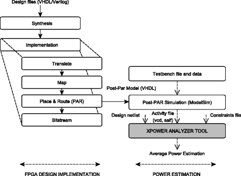
Power characterisation methodology using XPower Analyzer tool from Xilinx
-
Clock frequency is 50 MHz (CLKperiod=20 ns)

Although the FPGA dynamic power consumption is linearly dependent on clock frequency, it also depends on intrinsic parameters of each processing block such as data quantization affecting the number of resources and thus power consumption. All these parameters have to be considered during power characterisation. Figure 5 shows a simplified representation of the system under study which includes a transmitter and a receiver that support channel coding-decoding and QAM and OFDM modulation-demodulation. All these blocks are compliant with the LTE standard for PDSCH.

Scheme of the baseband system under study
The average dynamic power consumption (in mW) related to different M-QAM modulations (M = 4, 16, and 64), several IFFT sizes and code block sizes are presented in Table 1. Moreover, the latency, corresponding to the processing time of each TX block, is also reported.
The same strategy has also been applied to the receiver processing blocks, and results have been reported in Table 2. Note that the turbo decoder latency highly depends on the block size and on the number of processing units (PU). The number of PU enables to optimize both latency and throughput as a function of the block size. It can also be noticed that the turbo decoder consumes a significant part of the average dynamic power at the receiver. Moreover, the FFT average dynamic power consumption is higher than IFFT one due to implementation options.
Once all processing blocks are fully characterized, power and latency informations are integrated into a high-level modelling and simulation tool such as Matlab.
3.3 Extension to other FPGAs
Although power estimation values are specific to an FPGA device and have been obtained under several assumptions, useful insights on how much energy is consumed in an actual circuit are provided. In order to extend the results previously obtained to other FPGAs, a scaling factor can be introduced according to the processing block and the type of device considered. Examples are provided in Table 3 for FIR filter, QAM modulator/demodulator, and IFFT. Power estimations have been obtained for several FPGA and different IP’s parameters. The scaling reference is the Virtex-4 dynamic power estimation (without considering inputs/outputs (I/O) power). In this way, the provided factors may be used to obtain more flexibility and generality to the detriment of a loss of accuracy due to averaging and scaling. The scaling factors have to be determined for different IPs within the system.
4 System performance analysis
4.1 System parameters
This section presents the energy efficiency performance of the LTE-A system using relays and HARQ-CC/IR mechanisms. The mother code rate R c for HARQ-IR is 4/5 and the coding rate in HARQ-CC scheme is set to 1/3. For our simulations, BS communicates with UE either by a direct transmission or with the help of RN. A strong line-of-sight (LOS) in BS-RN link is assumed, and channel parameters are specified in Table 4. The multi-path channel model in BS-UE and RN-UE links is the extended pedestrian A (EPA) model defined in Table 5. We also assume that BS, RN, and UE are collinear, and the distance between BS and UE is 300 m. RN is placed at 150 m from BS, and the transmission power at RN is set to half of the BS transmission power [36]. For AF protocol, the transmission power at RN is adapted as described in Section 2.2. The path-loss propagation models w.r.t. the link distance R adopted in these simulations are listed in Table 6. The system simulation parameters are presented in Table 7 and are used throughout this section. Moreover, the static RF power consumption is set to 26 dBm that could correspond to the power consumed by a single user in a small cell environment.
4.2 Performance of DF protocol
4.2.1 Energy efficiency in bits/joule
In Figs. 6 and 7, the energy efficiency (bits/joule) for HARQ-CC and HARQ-IR is depicted as a function of transmission power in dBm. In these figures, the dynamic power consumption related to the baseband processing PDYN,BB, is only considered. At low transmission power, EE for all schemes is very low due to a low successful decoding probability. However, as transmission power increases, EE starts increasing. For instance in Fig. 6, we observe that DF relaying can achieve a larger EE compared to direct transmission. Indeed, from −4 to 22 dBm, cooperative HARQ-CC achieves a plateau around 3 Mbits/J using 4-QAM, 16-QAM, and 64-QAM. As per transmit power increases, the successful decoding probability at RN increases and hence the delay decreases leading to a better EE compared to direct transmission for which the transmit power is not enough to ensure a correct decoding at UE. For both direct or cooperative protocols, EE reaches a maximum as the transmission power increases. This maximum is larger for direct communication than for cooperative one, about 1.85, 1.7, and 1.6 times for 4, 16, and 64 QAM, respectively. In fact, for high SNR, RN consumes additional but useless energy. If the transmission power keeps increasing, EE decreases for all configurations since the probability of successful decoding at UE approaches one and the average delay achieves one time slot. Hence, no more gain in energy can be expected from the delay reduction, and high transmission power penalizes the energy efficiency of the transmission. The same type of analysis can be conducted for HARQ-IR. However, we can observe a “smoother” shape of the plateau region in that case, and the difference between the maximum EE of the direct transmission compared to cooperative is less important.

Energy efficiency versus transmit power in dBm. The HARQ-CC protocol is used. Direct and cooperative transmissions are considered, and the adopted modulations are: 4, 16, and 64 QAM. PDYN,BB is only taken into account in the energy efficiency computation

Energy efficiency versus transmit power in dBm. The HARQ-IR protocol is used. Direct and cooperative transmissions are considered, and the adopted modulations are: 4, 16, and 64 QAM. PDYN,BB is only taken into account in the energy efficiency computation
Compared to Figs. 6 and 7, for which PDYN,BB, is only considered, Figs. 8 and 9 show EE evaluation by also taking into account PST,BB and PST,RF for both HARQ-CC, HARQ-IR, respectively. It can be first noticed that EE is globally lower when all sources of power consumption are considered (roughly one order of magnitude). Another striking observation in Figs. 8 and 9 is that the plateau value strongly depends on the modulation order. Since the average delay depends on the chosen modulation order, EE also depends on modulation.

Energy efficiency versus transmit power in dBm. The HARQ-CC protocol is used. Direct and cooperative transmissions are considered, and the adopted modulations are: 4, 16, and 64 QAM. PDYN,BB+PST,BB+PST,RF are taken into account in the energy efficiency computation

Energy efficiency versus transmit power in dBm. The HARQ-IR protocol is used. Direct and cooperative transmissions are considered, and the adopted modulations are: 4, 16, and 64 QAM. PDYN,BB+PST,BB+PST,RF are taken into account in the energy efficiency computation
Moreover, it can be observed that the difference between the maximum EE achieved in direct and cooperative transmission is relatively small in this case. For instance, in HARQ-CC protocol and 64-QAM modulation, 1.5 Mbits/J is achieved in direct communication and 0.8 Mbits/J when using relay. The difference is even smaller for 16 and 4-QAM. For the latter, there is almost no benefit to employ direct communication; relaying strategy is always beneficial. Performance with HARQ-IR behaves in a same way and there is little advantage to employ direct communication instead of cooperation. However, one can remark that the maximum EE is achieved for 16-QAM in direct communication, i.e., 1.8 Mbits/J at P t =31 dBm, against 1.55 Mbits/J for cooperation and the EE achieved for 64-QAM and 4-QAM are lower.
In order to highlight the influence of the power consumption sources, EE is investigated by fixing modulation order, i.e., 16-QAM, and by adding progressively the different sources of power consumption. The results are summarized in Fig. 10, where HARQ-CC and HARQ-IR protocols are both considered. For each HARQ technique and with/without relay, two cases of power consumption sources are considered, i.e., static powers (PST,BB+PST,RF) or static and dynamic powers (PDYN,BB+PST,BB+PST,RF). For instance, the red and blue curves (HARQ-IR) represent EE when the dynamic power related to the baseband processing is taken into account or not, respectively. For this configuration, we observe that EE obviously decreases when all sources of power consumption are taken into account. We therefore demonstrate that results of literature presented without taking into account PDYN,BB lead to optimistic performance. Moreover, the impact of PDYN,BB is even more important at low transmit power due to the predominance of static power consumption in that case. We also remark that HARQ-IR is more energy-efficient than HARQ-CC from medium to high transmit powers, but HARQ-CC outperforms HARQ-IR for very low transmit powers, i.e., from −5 to 2 dBm.

Energy efficiency versus transmit power in dBm for different EE computations. The HARQ-IR and HARQ-CC protocols are compared. Direct and cooperative transmissions are considered, and the adopted modulation is 16QAM. Dynamic power (DYN) related to the baseband processing is taken into account or not in the EE evaluation
To conclude and summarize this section, optimal modulation and HARQ protocol maximizing EE is investigated. According to the BS transmit power budget, the maximum achievable EE is drawn in Fig. 11 labelled with optimal modulation and retransmission protocol. This result is equivalent to maximize (2) over the set of modulation and protocols under average BS transmit power constraint. We note an interesting behaviour around 30 dBm where EE max is achieved for IR-16QAM instead of IR-64QAM. This behaviour can be understood only when dynamic FPGA power consumption is taken into account. This is due to the contributions of (9) and (10) in (2) when modulation goes from 16 to 64QAM. Indeed, the number of OFDM symbols needed to encode a certain number of information bits decreases when 64QAM is used compared to 16QAM. However, PER increases for large modulation order but does not compensate the decrease of energy consumption induced by limiting the number of packets to be sent and hence, IR-16QAM is better from 30 to 35 dBm.
4.2.2 Energy efficiency-spectral efficiency tradeoff
Generally, energy efficiency is not the only criterion to optimize in wireless access network. Moreover, it is well known that EE and SE are two conflicting metrics and that EE-SE is a Pareto front delimiting feasible regions in terms of rates and energy efficiencies [33, 37, 38]. Figure 12 depicts the EE-SE trade-off for the DF-relaying protocol using HARQ-IR and HARQ-CC. In this simulation, all sources of power consumption are taken into account, i.e., static and dynamic. For low values of SE, EE behaves almost linearly w.r.t. SE and then sharply decreases when the transmit power increases, i.e., when SE increases. This behaviour, which has been reported in several other works, e.g., [39, 40], is explained by the presence of static power consumptions, i.e., independent of the transmit power, counterbalancing the natural conflicting behaviour of EE and SE. Indeed, at low transmit power, i.e., low SE, the static parts are predominant and hence increasing the transmission power results in an increase of both SE and EE. However, as the transmit power becomes higher, it exceeds static powers and becomes the main source of energy waste leading to an important decrease in EE. As shown on Fig. 12, HARQ-IR enables to reach higher EE-SE w.r.t. HARQ-CC for a given modulation format. For 16QAM, the maximum EE obtained with HARQ-IR is about 1.5 Mbits/J for SE equal to 2.1 bits/s/Hz and 1.08 Mbits/J with HARQ-CC for SE equal to 0.9 bits/s/Hz. The interest of incremental redundancy in EE is enlightened by this result. This is mainly due to the efficient use of retransmission opportunities compared to HARQ-CC which retransmits the same packet with a code rate about 1/3. At the contrary, HARQ-IR first transmits with a high coding rate, i.e., 4/5, and then retransmits additional redundancy bits if needed, which is more energy-efficient.

Maximum of energy efficiency versus transmit power: cooperative transmissions are allowed as well as HARQ-CC and HARQ-IR protocols with three modulation formats: 4, 16, and 64QAM; PDYN,BB+PST,BB+PST,RF are considered

Energy efficiency versus spectral efficiency. HARQ-CC and IR protocols are used. Cooperative transmissions are considered, and the adopted modulations are : 4, 16, and 64QAM. PDYN,BB+PST,BB+PST,RF are taken into account in the energy efficiency computation
4.3 Energy efficiency of AF and DF relaying
In this section, EE of AF- and DF-relaying protocols are investigated w.r.t. transmission power. The modulation scheme is set to 4QAM and will be used throughout this section unless otherwise mentioned.
Figures 13 and 14 present EE w.r.t. transmission power for \(N_{\max } = 2\) and 6, respectively and HARQ-CC. On these plots, three zones can be observed, i.e., two inefficient energy zones at very low/high transmission power and an efficient energy zone at medium transmission power. At very low transmission power, the energy spent is not sufficient to ensure a correct packet transmission and hence the error probability is very high leading to poor EE. As per transmission power increases, both protocols, i.e., AF and DF enable increasing EE with advantage to AF compared to DF for \(N_{\max } = 2\). In Fig. 13, around −4 dBm for DF and 0 dBm for AF, EE reaches a plateau at 0.59 Mbits/J in AF against 0.32 Mbits/J in DF, until 20–25 dBm transmit power for both. From 25 dBm, EE severely decreases for both protocols due to a too high amplifier power consumption.

Energy efficiency for AF and DF versus transmit power in dBm (\(N_{\max } = 2\)). The HARQ-CC protocol is used, and the adopted modulation order is 4QAM. PDYN,BB+PST,BB+PST,RF are taken into account in the energy efficiency computation

Energy efficiency for AF and DF versus transmit power in dBm (\(N_{\max } = 6\)). The HARQ-CC protocol is used, and the adopted modulation order is 4QAM. PDYN,BB+PST,BB+PST,RF are taken into account in the energy efficiency computation
Considering \(N_{\max } = 6\) in Fig. 14, the same behaviour with approximatively the same EE values than in Fig. 13 can be observed. However, at low transmission power, we can notice that DF slightly outperforms AF during a small range of transmission power, i.e., from −10 to −6 dBm. This is due to the very low probability for the UE to ACK a packet in AF protocol at these transmission power levels resulting in a poor EE. On the other hand with DF, the RN node can possibly decode the packet and forward it, reducing the travelling distance for the packet. This results in a higher success probability at the UE. In Figs. 13 and 14, AF outperforms DF in medium range of transmission power due to the absence of the static and dynamic baseband power consumption in AF and also because packet delivery requires two time slots in DF.
5 Conclusions
In this paper, energy efficiency of AF- and DF-relaying techniques with retransmission protocols has been investigated. Using a real FPGA target and a dedicated tool, i.e., XPA, the power consumption of the main components of an LTE-based baseband has been taken into account, as turbo encoder/decoder, symbol mapping/demapping, and IFFT/FFT blocks. This power consumption, referred as dynamic power consumption, is generally omitted resulting in optimistic EE performance presented in literature. The power consumption of each block has been integrated on a global energy consumption model taking into account relaying techniques and HARQ-CC/IR protocols. EE-SE trade-off of DF and HARQ-CC/IR protocols has been characterized. From our investigations, several useful insights and recommendations can be drawn: (1) HARQ-IR with DF relaying scheme achieves the best EE-SE trade-off compared to HARQ-CC due to the efficient use of retransmission slots; (2) AF outperforms DF in terms of EE since the static and dynamic baseband power consumptions are absent in AF and also because packet delivery requires two time slots in DF; moreover, relaying schemes are much more energy-efficient than direct transmission at low signal-to-noise ratio; this study gives very useful insights about which HARQ retransmission protocol and relay-assisted scheme should be adopted in future green wireless networks (3) power consumption related to baseband processing should be taken into account by engineers in order to get realistic energy efficiency values especially when low transmission power is considered in a small cell. Moreover, this study enables to quantify the power consumption of FPGA-based systems. Scaling factors were introduced to make easier the power estimation for different FPGA families. FPGA devices are an interesting technology in order to support the growing complexity and highly constrained domain of future wireless communication systems. As further work, full-duplex transmission technique will be investigated as a promising solution to overcome the latency induced by slotted DF protocols. In parallel, multi-user scenarios will also be taken into account.
References
WV Heddeghem, S Lambert, B Lannoo, D Colle, M Pickavet, P Demeester, Trends in worldwide ICT electricity consumption from 2007 to 2012. Comput. Commun.50:, 64–76 (2014).
B Lannoo, Assessment of power consumption in ict. Technical report, FP7 TREND technical report D1.6 Final WP1 (2013).
MA Imran, et al, Most suitable efficiency metrics and utility functions. Technical report, INFSO-ICT-247733 EARTH (2011).
O Blume, et al, Most promising tracks of green network technologies. Technical report, INFSO-ICT-247733 EARTH (2011).
B Gergely, et al, Economic and ecological impact of ICT. Technical report, INFSO-ICT-247733 EARTH project deliverable D2.1 (2012).
DSW Hui, VKN Lau, WH Lam, Cross-layer design for OFDMA wireless systems with heterogeneous delay requirements. IEEE Trans. Wirel. Commun.6(8), 2872–2880 (2007).
D Zhang, Y Wang, J Lu, QoS aware relay selection and subcarrier allocation in cooperative OFDMA systems. IEEE Commun. Lett.14(4), 294–296 (2010).
M Maaz, P Mary, M Helard, in Cross Layer Design (IWCLD), 2011 Third International Workshop On. Resource allocation for QoS aware relay-assisted OFDMA cellular networks, (2011), pp. 1–6.
S McLaughlin, PM Grant, JS Thompson, H Haas, DI Laurenson, C Khirallah, Y Hou, R Wang, Techniques for improving cellular radio base station energy efficiency. IEEE Wirel. Commun.18(5), 10–17 (2011).
Z Niu, Y Wu, J Gong, Z Yang, Cell zooming for cost-efficient green cellular networks. IEEE Commun. Mag.48(11), 74–79 (2010).
J Hoydis, M Kobayashi, M Debbah, Green small-cell networks. IEEE Veh. Technol. Mag.6(1), 37–43 (2011).
Z Niu, S Zhou, Y Hua, Q Zhang, D Cao, Energy-aware network planning for wireless cellular system with inter-cell cooperation. IEEE Trans. Wirel. Commun.11(4), 1412–1423 (2012).
D Cao, S Zhou, C Zhang, Z Niu, in Global Telecommunications Conference (GLOBECOM 2010), 2010 IEEE. Energy saving performance comparison of coordinated multi-point transmission and wireless relaying, (2010), pp. 1–5.
J Xu, L Qiu, C Yu, Improving network energy efficiency through cooperative idling in the multi-cell systems. EURASIP J. Wirel. Commun. Netw.2011:, 165 (2011).
S Han, C Yang, G Wang, M Lei, in Personal Indoor and Mobile Radio Communications (PIMRC), 2011 IEEE 22nd International Symposium On. On the energy efficiency of base station sleeping with multicell cooperative transmission, (2011), pp. 1536–1540.
X Wang, P Krishnamurthy, D Tipper, in Wireless Communications and Networking Conference (WCNC), 2012 IEEE. Cell sleeping for energy efficiency in cellular networks: Is it viable? (2012), pp. 2509–2514.
H Holtkamp, G Auer, H Haas, in Vehicular Technology Conference (VTC Fall), 2011 IEEE. On Minimizing Base Station Power Consumption, (2011), pp. 1–5.
3rd Generation Partnership Project - LTE-A, Technical Specification Group Radio Access Network; Evolved Universal Terrestrial Radio Access (E-UTRA); Physical layer for relaying operation (Release 12). Technical report, 3 GPP - LTE-A Technical Report (2014).
3rd Generation Partnership Project - LTE-A, Technical Specification Group Radio Access Network; Evolved Universal Terrestrial Radio Access (E-UTRA); Relay architectures for E-UTRA (LTE-Advanced) (Release 9). Technical report, 3 GPP - LTE-A Technical Report (2013).
I Stanojev, O Simeone, Y Bar-Ness, K Dong Ho, Energy efficiency of non-collaborative and collaborative Hybrid-ARQ protocols. IEEE Trans. Wireless Commun.8(1), 326–335 (2009).
Y Qi, R Hoshyar, MA Imran, R Tafazolli, H2-ARQ-relaying: Spectrum and energy efficiency perspectives. IEEE J. Sel. Areas Commun.29(8), 1547–1558 (2011).
R Gupta, EC Strinati, in 22nd International Symposium on Personal Indoor and Mobile Radio Communications (PIMRC), 2011 IEEE. Green scheduling to minimize Base station transmit power and UE circuit power consumption, (2011), pp. 2424–2429.
H Yu, Y Li, M Kountouris, X Xu, J Wang, Energy efficiency analysis of relay-assisted cellular networks. EURASIP J. Adv. Signal Process.2014(1), 32 (2014).
Y Hu, J Gross, A Schmeink, QoS-constrained energy efficiency of cooperative ARQ in multiple DF relay systems. IEEE Trans. Veh. Technol.PP(99), 1–1 (2015).
M Maaz, P Mary, M Helard, in Personal Indoor and Mobile Radio Communications (PIMRC), 2012 IEEE 23rd International Symposium On. Energy efficiency analysis in relay assisted hybrid-ARQ communications, (2012), pp. 2263–2268.
C Sun, C Yang, Energy efficiency analysis of one-way and two-way relay systems. EURASIP J. Wirel. Commun. Netw.2012(1), 46 (2012).
G Auer, et al, Energy efficiency analysis of the reference systems, areas of improvements and target breakdown. Technical report, EARTH project deliverable D2.3 (2012).
C Desset, B Debaillie, V Giannini, A Fehske, G Auer, H Holtkamp, W Wajda, D Sabella, F Richter, MJ Gonzalez, H Klessig, I Godor, M Olsson, MA Imran, A Ambrosy, O Blume, in Wireless Communications and Networking Conference (WCNC), 2012 IEEE. Flexible power modeling of LTE base stations, (2012), pp. 2858–2862.
Xilinx Inc., XPower estimator user guide (2014). User Guide UG440 (v13.4) http://www.xilinx.com/support/documentation/sw_manuals/xilinx2014_1/ug440-xilinx-power-estimator.pdf. Accessed date January 2016.
D Chase, Code combining–A maximum-likelihood decoding approach for combining an arbitrary number of noisy packets. IEEE Trans. Commun.33(5), 385–393 (1985).
B Maham, A Behnad, M Debbah, Analysis of outage probability and throughput for half-duplex hybrid-ARQ relay channels. IEEE Trans. Veh. Technol.61(7), 3061–3070 (2012).
M Dohler, Y Li, Cooperative Communications: Hardware, Channel & PHY, (2010).
EV Belmega, S Lasaulce, M Debbah, in IEEE 22nd Int. Symp. on Personal Indoor and Mobile Radio Commun. (PIMRC), 2011. A survey on energy-efficient communications, (2011), pp. 1–5.
Xilinx Inc., ISE Design Suite. Website. www.xilinx.com/products/design-tools/ise-design-suite.html. Accessed date January 2016.
Mentor Graphics, ModelSim Simulation Tool. Mentor Graphics website. www.mentor.com/products/fv/modelsim/. Accessed date January 2016.
B Furht, SA Ahson. Long term evolution: 3GPP LTE radio and cellular technology (Auerbach Publications, (CRC Press), 2009).
R Zhang, O Berder, J-M Gorce, O Sentieys, Energy-delay tradeoff in wireless multihop networks with unreliable links. Ad Hoc Netw.10(7), 1306–1321 (2012).
F Heliot, MA Imran, R Tafazolli, On the energy efficiency-spectral efficiency trade-off over the mimo rayleigh fading channel. IEEE Trans. Commun.60(5), 1345–1356 (2012).
AM Alam, P Mary, J-Y Baudais, X Lagrange, in Vehicular Technology Conference (VTC Fall), 2015 IEEE 82th. Energy efficiency-spectral efficiency tradeoff in interference-limited wireless networks with shadowing, (2015), pp. 1–5.
C He, B Sheng, P Zhu, X You, GY Li, Energy- and spectral-efficiency tradeoff for distributed antenna systems with proportional fairness. IEEE J. Sel. Areas Commun.31(5), 894–902 (2013).
Acknowledgements
The authors would like to thank Orange Labs for their financial contribution to these studies.
Author information
Authors and Affiliations
Corresponding author
Additional information
Competing interests
The authors declare that they have no competing interests.
Rights and permissions
Open Access This article is distributed under the terms of the Creative Commons Attribution 4.0 International License(http://creativecommons.org/licenses/by/4.0/), which permits unrestricted use, distribution, and reproduction in any medium, provided you give appropriate credit to the original author(s) and the source, provide a link to the Creative Commons license, and indicate if changes were made.
About this article

Cite this article
Maaz, M., Lorandel, J., Mary, P. et al. Energy efficiency analysis of hybrid-ARQ relay-assisted schemes in LTE-based systems. J Wireless Com Network 2016, 22 (2016). https://doi.org/10.1186/s13638-016-0520-9
Received:
Accepted:
Published:
DOI: https://doi.org/10.1186/s13638-016-0520-9