- Research
- Open access
- Published:
Performance evaluation of multiple-antenna IEEE 802.11p transceivers using an FPGA-based MIMO vehicular channel emulator
EURASIP Journal on Wireless Communications and Networking volume 2012, Article number: 215 (2012)
Abstract
The IEEE 802.11p standard has been optimized for low-delay small-bandwidth wireless communications to provide vehicular safety services. However, IEEE 802.11p transceivers can considerably improve their robustness by incorporating MIMO transmission methods. Moreover, multiple antennas can also be used to increase the data transfer rate of IEEE 802.11p transceivers, a requirement necessary to implement, for instance, non-critical safety applications. In this article we describe the design and development of a multiple-antenna IEEE 802.11p performance evaluation system made of two IEEE 802.11p software-based transceivers and two different, flexible low-cost FPGA-based multi-antenna channel emulators. Our channel emulators are able to recreate seven vehicular communication environments including highways, urban canyons and suburban areas. Using our performance evaluation system, we obtained performance curves showing that IEEE 802.11p can dramatically improve its performance by using multiple transmit and receive antennas. In addition, our channel emulators accelerated the performance evaluation task between 6 and 209 times compared to that of conventional software-based simulation approaches.
Introduction
In recent years vehicular communications have received a great deal of attention due to the increasing demand for new applications. This kind of communications, whose operation lies in the area of Intelligent Transportation Systems (ITS), usually requires the exchange of messages between vehicles (Vehicle-to-Vehicle or VTV communications) or between a vehicle and a roadside unit (Road-to-Vehicle or RTV communications). There are basically two sorts of vehicular applications: those dedicated to providing safety services and those that do not. The former require a fast exchange of messages in order to obtain a swift reaction from the car or the driver in dangerous situations. IEEE 802.11p [1] is probably the best positioned standard for providing safety services since it has been explicitly optimized for such kind of communications.
On the contrary, non-safety services do not have so tight time restrictions and usually require higher data transfer rates. Non-safety applications include, for instance, mobile internet access, roadsign recognition or travel information management. If IEEE 802.11p has to provide such kind of services in vehicular environments, its throughput and robustness have to be improved in order to compete with standards like IEEE 802.16e (Mobile WiMAX) or long-term evolution (LTE).
One of the best ways to increase the transmission capacity and the reliability of a wireless system consists in using multiple antennas at transmission [known as multiple-input single-output (MISO) systems], reception [single-input multiple-output (SIMO) systems] or both at transmission and reception [multiple-input multiple-output (MIMO) systems] [2, 3]. IEEE 802.11p was initially devised as a single-antenna [single-input single-output (SISO)] system, so it is of great interest from a communication system designer point of view to evaluate in realistic scenarios transceivers based on IEEE 802.11p but including multiple antennas.
Note that IEEE 802.11p is an amendment to the IEEE 802.11 standard that specifies the extensions for wireless local area networks in order to provide wireless communications in a vehicular environment. Such amendment is based on IEEE 802.11-2007 as amended by IEEE 802.11k-2008, IEEE 802.11r-2008, IEEE 802.11y-2008, IEEE 802.11n-2009, and IEEE 802.11w-2009. Hence, being IEEE 802.11n one of the amendments, the idea of applying multiple-antenna techniques in IEEE 802.11p can be easily carried out in future releases of the standard through a new amendment.
In order to assess the performance of new wireless communication systems it is desirable to evaluate them in realistic situations. Tests may be performed directly in a vehicle, driving through different environments, but that is a time-consuming task and the experiments can be affected by unintended side effects. It is more convenient to use a real-time hardware channel emulator and measure the performance inside a testing lab. This way, time and cost is saved and all the parameters involved in the experiment remain under control.
Channel emulation can be carried out by using hardware, software or implementing a hybrid approach. Hardware channel emulators are commonly used to evaluate hardware transceivers, while software channel emulation is widely used by researchers when the transceiver whose performance is being assessed is also software-based. The price to be paid when using the software-based approach is that software simulations may take a long time if the channel to be emulated consists of several paths with specific behaviors, as occurs with realistic wireless channel models.
Nevertheless, the concept of software-hardware co-simulation suggests a new hybrid approach: the transceivers can be implemented in software, giving researchers absolute configuration control and flexibility, whereas the channel emulation can be run on hardware, thus accelerating channel emulation and the overall simulation process. Obviously, the time required for developing a hardware emulator is larger than in the software-based case, but if the channel emulation is run an extremely high number of times, the time savings related to simulation eventually compensate for the development time.
These reasons motivated us to develop two different channel emulators that follow this software-hardware co-simulation approach: we consider wireless communication testing platforms where the transceivers are entirely software-based but the channel emulators run in an Field-Programmable Gate Array (FPGA). In order to reduce the development time, we have made use of rapid-prototyping tools both for software (Matlab/Simulink) and hardware (Xilinx System Generator), which allowed us to build and refine the channel emulator really fast in comparison with other traditional tools (e.g. hardware description languages).
We have previously assessed transceiver performance in co-simulation mode in [4]. In the present article we depart from the implementations described in such article and we show how we have upgraded the whole system with the goal of carrying out performance comparisons for multiple-antenna transceivers. Furthermore, we present a second MIMO 2×2 channel emulator based on novel channel parameters recently proposed in [5].
The rest of this article is organized as follows. Section “Background” gives a comprehensive overview of the latest mobile channel models and FPGA-based MIMO channel emulators. Section “Performance evaluation systems” describes the vehicular MIMO channel emulators and presents the implemented multiple-antenna software transceiver. Finally, Section “Experimental results” details the experiments performed, whereas Section “Conclusions” is devoted to the conclusions.
Background
Mobile and vehicular channel models
References [6–24] describe different mobile and vehicular channel models that try to reflect the continuously changing conditions of the environment. Most of these models have been developed for SISO transceivers [6–8, 10, 11, 13–15, 18, 19, 21, 23, 24], while a few are specific for multiple-antenna systems [9, 12, 16, 17, 20, 22]. These vehicular models can be also classified depending on the way they were obtained, distinguishing physical (PHY) models [6–8, 15–17, 20–24], empirical models [11–14, 18, 19] and models that mix empirical measurements and PHY developments [9, 10].
Physical models characterize an environment by analyzing the propagation of electromagnetic waves between a transmitter and a receiver. Such models can be very sophisticated and usually require indicating several parameters in order to reproduce accurately the propagation in a specific scenario. Moreover, this kind of models does not depend on the characteristics of the antenna array (number of antennas, polarization, etc.) or the system bandwidth.
Geometry-based stochastic channel models (GSCM) are probably the most popular PHY channel models. A good example is [17], which describes a 3D wideband channel model for MIMO transceivers that carry out mobile communications.
In regard to empirical vehicular models, it can be observed that most of them have been obtained for the 5 GHz band [9–12, 14, 18, 19], although there are also models for the 2.4 GHz band (e.g. [13]). Vehicular communications mostly take place in the 5 GHz band: in 1999, the dedicated short range communications (DSRC) spectrum band, a band of 75 MHz at 5.9 GHz, was allocated in the United States, whereas, an equivalent band was allocated in Europe in August 2008 by the European Telecommunications Standards Institute (ETSI) (such entity reserved 30 MHz of spectrum in the 5.9 GHz band for ITS). Nevertheless, our channel emulators cover both the 5 GHz frequency band (see Section “FPGA-based MIMO channel emulator built by upgrading our previous SISO vehicular channel emulator”) and 2.4 GHz (see Section “FPGA-based MIMO channel emulator for the new MIMO 2 × 2 Acosta’s channel model”).
Empirical models are created by analyzing measurements obtained when transmitting over a real environment and then modeling the channel characteristics. Sometimes researchers are not satisfied with the accuracy of their empirical model and they add analytical developments (such as the ones performed for PHY channel models), creating mixed models. For instance, [9] presents a wideband MIMO vehicular channel model based on a GSCM and 5.2 GHz measurements performed in highways and rural areas.
From all the above-mentioned vehicular models, we decided to use the empirical models described in [5, 14] for three reasons:
-
They represent real-world situations and, therefore, contemplate all the factors that influence transmissions in a real vehicular scenario.
-
They are far less complex than most of PHY models that control the same amount of communication parameters.
-
They have been traditionally used by the industry to evaluate commercial transceivers. For instance, standards such as IEEE 802.16e and IEEE 802.11n or 3G/beyond-3G telephony have proposed empirical models for the evaluation of their transceivers [25–27].
Of course, the use of empirical channel models have disadvantages: they are difficult to generalize (although there exist hybrid models that mix empirical and theoretical contributions (e.g. [9])) and they are less accurate than other kinds of models (e.g. PHY models) in certain situations, since they usually require approximations.
Finally, note that the channels modeled in [14] are based on SISO measurements, but we use them because they have been suggested as a reference for evaluating IEEE 802.11p transceivers. Further investigation is still needed to adapt such channels to multiple-antenna environments, but when that occurs, the transceivers and the channel emulator model presented in this article will continue to be valid.
MIMO channel emulators
There are two kinds of MIMO emulators: commercial and academic. On the one hand, there are many commercial MIMO emulators manufactured by companies such as Azimuth Systems [28], Agilent [29], Rhode & Schwarz [30], Spirent [31] or Propsim [32]. Most of their MIMO emulators are general-purposed (for instance, Spirent’s SR5500, Rhode’s AMU200A, Propsim’s F8 MIMO OTA or the ACE MX family from Azimuth), although there are some aimed at evaluating specific technologies, like Azimuth’s ACE-400WB/Wi-Fi (that includes the TGn channel models [25] for evaluating IEEE 802.11n transceivers) or Agilent’s N5106A PXB MIMO Receiver Tester (with built-in LTE and MobileWiMAX channels).
Although commercial emulators work great in most situations, they are expensive and suffer from a clear lack of flexibility when used by researchers to study performance in state-of-the-art wireless channels. The lack of flexibility is mainly in regard to the configuration of non-standard characteristics of the channel (i.e. the number of paths and taps, the fading spectral shapes, the fading Doppler, etc.). Additionally, another important issue arises in the case of vehicular channels: several well-known researchers [5] state that the main characteristics of a VTV channel resides in the non-constant characteristic of the K-factor, which current channel emulators do not support.
On the other hand, apart from commercial products, several authors have described how they built their own channel emulators. Among the available technologies, microcontrollers and digital signal processors (DSPs) are not valid due to processing and real-time constraints, while application-specific integrated circuits (ASICs) are discarded since their development time is too high for a prototype (although they offer better performance). Thus, the choices could be reduced to complex programmable logic devices (CPLDs) and FPGAs. CPLDs can execute tasks at a faster rate, but FPGAs can deal with more complex designs and they own specific resources (such as counters or arithmetic operator blocks) that are more adequate for implementing a channel emulator. Due to the facts mentioned, FPGAs are probably the most popular hardware technology for developing channel emulators.
Examples of academic MIMO FPGA-based channel emulators are described in [33–40]. Some of them are generic [33–35, 38], while others [36, 37, 39, 40] are specifically oriented towards the implementation of the IEEE 802.11n channels [25]. We would like to point out that none of the studied channel emulators have been explicitly developed for recreating VTV or RTV environments.
One of the main problems when implementing MIMO channel emulators in an FPGA is that they require large designs and, therefore, the use of resources has to be optimized. Although most of the studied channel emulators are able to implement the whole system into only one FPGA, there are examples of channel emulators that distribute computing among different FPGAs [40]. Furthermore, to fit the design into one FPGA, researchers have to save resources using different clever tricks, being one of the most recurrent the off-line generation of the channel coefficients [33, 36, 37, 39]. Also, some authors [37] achieve to save up to 67% of the FPGA resources by applying the channel coefficients in the frequency domain.
Moreover, it is quite common to implement a Jakes’ simulator (which makes use of the sum-of-sinusoids method) to obtain a good trade-off between performance, used resources and development time (e.g. [41]). However, although it has been successfully used in the last 40 years, its limitations are still not well understood [42] and it has problems for creating multiple uncorrelated fading waveforms for frequency selective fading channels and MIMO channels [43]. In fact, different modifications of the Jakes simulator have been proposed to correct such issues and implement Rice/Rayleigh fading channels (e.g. [44]).
We have detected at least three drawbacks in the above-mentioned academic developments. First, the use of low-level description languages such as very high speed integrated circuit hardware description language (VHDL) results in slow development stages. Although in most cases VHDL is able to obtain resource-efficient FPGA designs, programming can become a cumbersome task that may consume a large amount of time and economic resources. There are new sophisticated tools such as Xilinx System Generator that permit the use of high-level blocks, enabling to build complex designs easier and faster. However, it must be noted that although rapid-prototyping tools increase development speed, they usually generate non-optimized large designs that may not fit into the FPGA. Hence, for large designs, optimizations must be performed.
The second problem we have found is related to the portability of the channel emulator. An ideal channel emulator should be able to work in a stand-alone mode, without needing external devices to generate and transfer channel coefficients to the FPGA. In the reviewed literature PCs are commonly used to generate coefficients [33, 36, 37], although some authors have been able to build more compact systems by using other devices (for instance, in [39] coefficient generation is performed by an ARM9 processor). Moreover, there is a bottleneck in the number of coefficients that can be transferred from the external device to the FPGA (either due to restrictions on the external device or on the communication buses), what leads to important limitations. For example, in [39] the externally generated coefficients are stored into a Zero Bus Turnaround RAM (ZBT-RAM) and then sent to the emulator, which is only able to apply such coefficients through a two-minute time interval.
The third drawback of the studied channel emulators is related to scalability. As it can be derived from the results shown in [37], when we work with a time-domain based channel emulator, the gate count (i.e. the number of 2-NAND logic gates that would be required to implement the same number and type of logic functions) roughly doubles every time we add a transmit and a receive antenna to the system. Therefore, a scalable solution would have to be able to deal with more inputs and outputs without requiring such important hardware complexity increases.
In this article we propose two different approaches aimed at solving the mentioned drawbacks. Both of them make use of Xilinx System Generator to develop highly-configurable channel emulators faster than using an HDL. The System Generator designs are optimized to fit twelve to twenty-four complex path channel emulators into one FPGA. Moreover, although both channel emulators were designed bearing in mind that they had to be able to work in a stand-alone mode, the emulator described in Section “FPGA-based MIMO channel emulator built by upgrading our previous SISO vehicular channel emulator” was specifically built to cause the lowest possible impact on resource-consumption in case of requiring additional transmit/receive antennas, therefore facilitating scalability.
Performance evaluation systems
In the next subsections we describe how to develop two similar evaluation systems whose main components are depicted in Figures 1 and 2, where transmitters and receivers exchange data with the vehicular channel emulators through the PCI bus.

Time-multiplexed evaluation system for multiple-antenna IEEE 802.11p transceivers.

Time-multiplexed MIMO 2×2 emulator model without buffering.
Both channel emulators have been implemented on a Virtex IV FPGA (XC4VSX35-10FF668). The FPGA is placed inside a Nallatech’s BenADDA-IV development kit which has the following main features: it allows the use of Xtreme-DSP slices of up to 400 MHz, it has two 14-bit ADCs and two 14-bit DACs (able to work up to 105 and 160 MSamples/s, respectively), 4 MB of ZBT-RAM and its internal clock reaches up to 105 MHz (the kit can also use an external clock). Furthermore, a very interesting feature of the kit is that it can be connected to a PC (via the PCI bus) or it can be used in stand-alone mode.
We made use of a rapid-prototyping tool (Xilinx System Generator) for developing the vehicular channel emulators. In order to evaluate multi-antenna systems we have taken advantage of one of the System Generator features: its ability to exchange data between a design running in the FPGA and a software implementation that is executed on a PC. In fact, during the measurements described in Section “Performance measurements” we used MATLAB/Simulink software transceivers while the vehicular channel emulator was running on an external FPGA.
IEEE 802.11p transceivers
The IEEE 802.11p standard is an amendment to IEEE 802.11-2007 [45] and is technically compatible with the specifications given by ASTM E2213-03 [46], which addresses the challenges that arise when providing wireless access in vehicular environments. Its medium access control (MAC) and PHY layers are very similar to those used in the wireless local area network IEEE 802.11a standard [47], but they have a lower overhead to allow faster exchanges of safety messages. A deep description of IEEE 802.11p is beyond the scope of this article, but we encourage the interested reader to take a look at the excellent overviews given in [48, 49].
To achieve full control on its PHY-layer, our IEEE 802.11p transceiver has been exclusively developed in software. In order to decrease the required development time we decided to use Matlab and Simulink for its implementation. Its design is pretty similar to the one detailed in [4], though several modifications were performed to make use of space-time diversity techniques.
Multiple-antenna transmitter
At the transmitter, the use of several antennas lead us to modify our SISO channel estimator to use orthogonal pilots that constitute matrices called Orthogonal Space-Time Pilot Matrices (OSTPM). Specifically, we use Hadamard matrices created using Sylvester’s method, which generates a sequence of matrices that are known as Walsh matrices. Such matrices are orthogonal in space and time and, in the case of transmitting with two antennas, are generated according to (1),
where p k is the BPSK-modulated pilot symbol transmitted at the k-th subcarrier. Since IEEE 802.11p uses four pilots for each OFDM symbol, the pilot matrix is generated by replicating (1) to obtain a 2×4 matrix. Using this scheme, channel estimation only requires simple linear processing, but it has several limitations. First, it assumes that the channel remains constant over two consecutive pilots, so for a sufficiently high Doppler spread performance will be degraded. The second drawback is related to the generation of the pilot matrix: it is only possible to use this pilot scheme when the number of transmit antennas is a power of two. Moreover, in order to make use of the channel estimation method, an even number of OFDM symbols has to be transmitted.
In spite of the above-mentioned issues, we decided to use this method due to its simplicity and because the maximum Doppler shift of the implemented channels is 1742 Hz. This means we can assume that the channel does not significantly vary within a time period of 574 μ s, which is higher than the time required to transmit two consecutive OFDM symbols (16 μ s).
Apart from the modifications required by the channel estimation MIMO systems need an additional coding stage to exploit space-time diversity. In the case of our 2×2 system we use Alamouti coding [50], whereas the 4×4 transceiver implements a quasi-orthogonal code proposed by Jafarkhani [51].
Multiple-antenna receiver
At the receiver side the main changes with respect to the SISO system are related to the support of diversity schemes. In the SIMO case we make use of the maximum-ratio combining (MRC) technique, whilst the MIMO transceiver includes an Alamouti decoder (for the 2×2 system) and a maximum-likelihood (ML) detector. We will not give any more details about the receivers since they use standard algorithms and techniques which are extensively covered by the existing literature (e.g. [52]).
FPGA-based MIMO channel emulator built by upgrading our previous SISO vehicular channel emulator
The first channel models we implemented on the FPGA-based vehicular emulator are described in [14]. There, the authors present channel models for six different 5.9 GHz high-speed environments that cover some of the most common situations where VTV and RTV communications may take place. Such channel models can be grouped into three major scenarios: urban canyons (VTV-Urban Canyon Oncoming RTV-Urban Canyon), expressways (VTV-Expressway Oncoming RTV-Expressway VTV-Expressway Same Direction With Wall) and suburban surface streets (RTV-Suburban Street). Urban canyons and suburban surface streets assume a speed of 120 Km/h, whereas the expressway measurements were made consistent with speeds of 140 Km/h. Table 1 shows the main characteristics of the models. For an extensive description of the channel characteristics we recommend consulting [53]. For a more extensive description of the SISO version of the vehicular emulator design and its characteristics, see references [4, 14].
Our first attempt to expand the SISO emulator to accept more input and output antennas consisted in creating a SIMO 1×2 system by replicating the SISO hardware. The design obtained was too large to fit into the FPGA, so we started to optimize it. For the sake of conciseness, we only cite below the three most important optimizations we carried out, whose savings are summarized in Table 2, where the more complex of the six designs (in terms of FPGA resources consumed) is used as a reference (VTV-Expressway Same Direction with Wall).
-
The first optimization reduced the amount of resources dedicated to perform the Doppler filtering stage (i.e. the stage aimed at applying each path’s Doppler spectrum) by using a four-output Doppler filter (see Figure 3). This is possible since every path uses the same Doppler filters. The resources occupied by this optimized version of the emulator are shown in Table 2 in the row for SIMO 1×2 (V1).
Figure 3 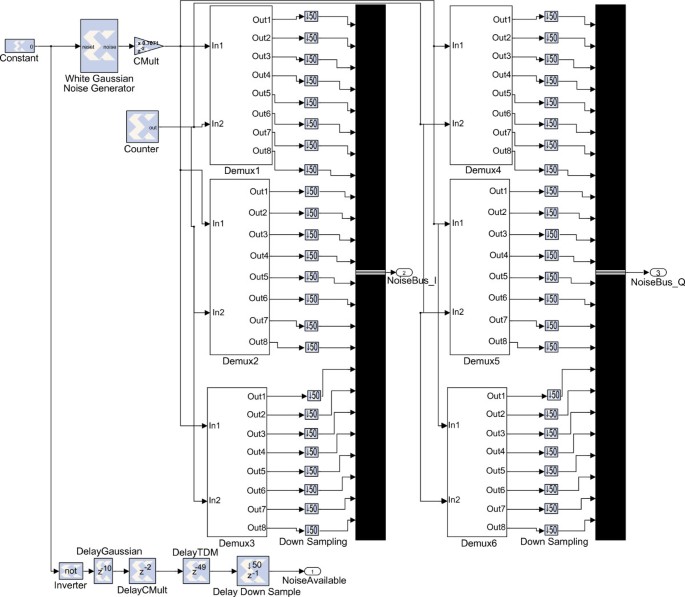
New Doppler filtering stage.
-
Our second optimization consisted in removing one of the two existing generators and creating a 50-output Gaussian generator (in Figure 4). Note that in a SIMO 1×2 we only need 48 outputs, but 50 is the closest integer divider of 20 MHz. The row SIMO 1×2 (V2) of Table 2 shows that the design was still too large to fit into the FPGA.
Figure 4 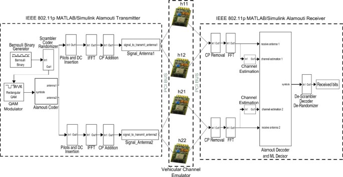
New Gaussian noise generator block.
-
The third optimization consisted in allowing every path to share Doppler filters, interpolators and FIR filters, being the generated Gaussian noise unique for each path. The row SIMO 1×2 (V3) of Table 2 shows that the used resources decreased substantially with respect to version V2 and that the design fitted into the FPGA, but it was clear that it would be very difficult to fit a MIMO 4×4 system (which has 8 times more paths than a SIMO 1×2 system) following the same optimization approach.


MIMO time-multiplexed approach
In order to solve the space issue there are several alternatives. The most obvious solution consists in purchasing a development kit with a larger FPGA, but that would increase the final cost of the emulator. Another solution could be the off-line generation of the channel coefficients, but then we would require a PC or an embedded device every time the vehicular channel emulator was used (i.e. the emulator would not be able to work in stand-alone mode). We could even refine the HDL code generated by System Generator, but that could take an important amount of time.
After considering all the alternatives, we finally decided to propose a scheme based on input and output buffers. Such buffers act similarly to two synchronized parallel-to-serial and serial-to-parallel converters. Each set of signals transmitted from an array of IEEE 802.11p transceivers are stored in a buffer and released at specific time instants, achieving a similar effect as if the parallel transceivers were executed in series. In Table 2, row MIMO 4×4, it can be seen the important resource savings attained by using the time-multiplexing approach, which even consumes 3% less slices than our old SISO version thanks to some of the previously described optimizations.
We would like to emphasize that although the resources consumed by the time-multiplexed approach have been indicated in Table 2 using the term MIMO 4×4, such resources would be the same for any system of up to four antennas at transmission and four antennas at reception. In fact, Section “Experimental results” presents the results of experiments carried out using the same time-multiplexed design but for transceivers with less than four antennas in transmission/reception (SIMO 1×2, SIMO 1×3, SIMO 1×4 and MIMO 2×2). Obviously, such systems do not use the whole memory offered by the input/output buffers, which is optimized for a MIMO 4×4, but the channel emulator design is the same for all of them.
It is also important to note that the input buffer has to add zeroes between each pair of signals that were transmitted by different antennas so as to reduce time correlation. In [4] we set the coefficient generation rate to frequencies that range between 2 and 4 KHz, so the shortest time the channel would remain almost constant would be 500 μ s. Therefore, if the FPGA clock is set to 20 MHz, the number of cycles that the channel coherence would remain constant would be 500 μ s/50 ns = 10,000. If we want to stay safe, we can wait for 100,000 cycles (5 ms) to guarantee minimal correlation. Hence, we separate each pair of signals by 5 ms. We tested this assumption by measuring the channel coefficient autocorrelation when transmitting 10,000 consecutive 64-subcarrier OFDM symbols and found no relevant correlations (the non-diagonal coefficients of the correlation matrix ranged approximately between 10−2 and 10−3).
FPGA-based MIMO channel emulator for the new MIMO 2 × 2 Acosta’s channel model
In 2010 some of the authors of the vehicular channels described in [14] used a similar methodology to present a novel vehicular MIMO channel model in [5]. There, it is described an empirical model for an urban environment around the Georgia Tech campus where a transmit vehicle travelled roughly 100 m ahead of the receive vehicle at a nominal speed of 56 Km/h (the actual speed ranged between 40 and 56 Km/h). The vehicles incorporated a MIMO 2×2 system that used 2.4 GHz co-located dual-polarized antennas. The authors modeled the channel and extracted characteristics for the four channel coefficients, whose main parameters are summarized in Table 3.
System design
The design of this MIMO 2×2 emulator is very similar to each of the models of Section “FPGA-based MIMO channel emulator built by upgrading our previous SISO vehicular channel emulator”, but there are several issues that had to be modified to adapt the model to the parameters specified in [5].
First, it must be noted that the model is made up of four channel coefficients that describe channels with up to 24 complex paths (there are only up to 12 complex paths in each model described in Section “FPGA-based MIMO channel emulator built by upgrading our previous SISO vehicular channel emulator”), what increases importantly the size of the FPGA design. In Table 4 it is exposed the amount of FPGA resources consumed by each channel coefficient design, that in some cases reaches the 99% of the total slices and more than 90% of some of the resources (hence, a MIMO emulator design does not fit into one FPGA). Furthermore, in this case the buffer-based time-multiplexed scheme described in the previous Section cannot be applied, since each channel coefficient cannot share its Doppler filtering stage (the Doppler effect parameters differ greatly from one coefficient to another). To solve this issue we designed a new time-multiplexed approximation (represented in Figure 2) where each transceiver antenna has to be synchronized in time with the emulator to send its signal when the emulator requires it.
In Table 4 it can be also observed that, in comparison to the models of [14] and due to the lower vehicular speeds, there exist lower Doppler frequencies, what leads to lower coefficient generation rates and higher interpolation factors. Note that the coefficients must adapt their rate to the rate of the incoming signal (i.e., the signal from the IEEE 802.11p transmitter that arrives at 10 MHz). These coefficients are generated at a rate that depends on the maximum Doppler shift and that is much lower than the FPGAs frequency. Indeed, in a specific vehicular channel, the implicit sample rate is twice the maximum Doppler shift of all paths. In the implemented vehicular channel models, this rate fluctuates between 446 and 738 Hz (see Table 4). To avoid designing a complex resampling stage, instead of using the original coefficient generation rate, we use an effective sample rate that is equal to the nearest integer divider of 10 MHz.
Besides, there is an important difference with respect to the upgraded SISO models: each of the 24 complex paths follows a Rayleigh distribution, there are no Rician components. It must be emphasized that although the authors of the models did not find significant K-factors when obtaining the power ratio between the fixed and the fluctuating components, they clearly state in [5] that they believe that one of the main characteristics of a VTV channel resides in the non-constant characteristic of the K-factor.
Coefficient generation process
Each complex coefficient is generated following a process that is very similar to the one detailed in [4]:
-
First, Gaussian noise is generated by a system like the one depicted in Figure 4. Each complex coefficient will be then conformed by a pair of Gaussian values with zero mean and unit variance.
-
Next, the coefficients of each path are filtered to apply the Doppler characteristics indicated by the model. The Doppler filtering stage is like the one shown in Figure 3, but only for two input/output signals instead of four.
-
After filtering, the coefficients are interpolated to adapt their rate to the signal that comes from the IEEE 802.11p transceivers at 10 MHz. To see an extensive description of the components and the functioning of the interpolation stage consult Section 3.5.4 in [4].
-
Finally, a complex FIR filter is used to apply the coefficients to the incoming signal (the System Generator design is similar to the one shown in Figure 5 of [4], but for up to 24 complex paths).

Channel estimation error for frequency-flat block fading Rayleigh channel for different Doppler frequencies.
Experimental results
Co-simulation versus software simulation lags
In order to quantify the speed improvements achieved by the proposed FPGA-based simulation models, we have compared its lags with the ones obtained when simulating using the Matlab/Simulink version of the vehicular channel emulators. The results are exposed in Table 5. Note that the lag is the time interval that goes by since a sample arrives at the input of the emulator until it is processed and placed at the output. Such lag is constant for every vehicular channel implemented. The study of the lags shows that the use of the co-simulation mode (a mode where the transceiver runs in Matlab/Simulink, whereas the emulator runs on the FPGA) dramatically increases the processing speed: each sample can be processed between 6 and 209 times faster than using the Simulink-based approach.
It is important to emphasize that such speed improvement factors are achieved even despite the fact that the co-simulation lag includes the time needed to transfer the signals through the PCI to/from the FPGA. Moreover, in the case of the channel models described in Section “FPGA-based MIMO channel emulator built by upgrading our previous SISO vehicular channel emulator”, the lag also includes 5 ms delays between each pair of transmitted signals.
Finally, we would like to point out that in the MIMO 2×2 channel emulator co-simulation lags vary for each channel coefficient depending on the complexity of its model. Thus, h 1,1, which is made up of 24 complex paths, has the highest lag, while h 1,2and h 2,1show the lowest lags because they are made of just 9 complex paths.
Performance measurements
Characteristics of the measurements
To evaluate the performance of the software transceivers we have passed their signals through the FPGA-based vehicular channel emulators taking advantage of the co-simulation mode. In order to achieve a fair comparison we have set the same transmission parameters for every transceiver and we have assumed that all of them send signals with the same transmission power. A rate 1/2 forward error correction (FEC) code was used and the OFDM subcarriers were filled with QPSK-modulated symbols. The receiver assumed perfect time synchronization and the channel was estimated using the OSTPM-based method described in Section “Multiple-antenna transmitter”. In the SISO systems an minimum mean-square error (MMSE) linear equalizer followed by an ML detector was used, while SIMO transceivers implemented the MRC technique. In the case of MIMO receivers, symbols were decoded if needed (an Alamouti decoder is used for 2×2 systems) and ML detectors were applied.
Performance in frequency-flat Rayleigh channel
In order to obtain a reference of the performance of the transceivers implemented, we evaluated them over a non-vehicular environment. Figures 6 and 7 show, respectively, the BER (Bit Error Rate) and FER (FEC block Error Rate) of the transceivers when transmitting over a spatially-uncorrelated frequency-flat block fading Rayleigh channel whose coefficients were constant during one FEC block.

Performance for frequency-flat block fading Rayleigh channel.

Performance for frequency-flat block fading Rayleigh channel.
It can be observed for both BER and FER that increasing the number of transmit and receive antennas greatly improves the performance of the SISO transceiver. If we take as a reference the SNR needed to obtain a FER of 10%, there exists a difference of 9 dB between the SISO system and the SIMO 1×4 or the MIMO 4×4. This implies that a SISO transceiver would require eight times more power than a SIMO 1×4 or a MIMO 4×4 to obtain the same FER.
Finally, it is also interesting to note that there is a difference of about 3 dB between the SIMO 1×4 and the MIMO 2×2 when comparing their BER curves. This effect happens because the MIMO 2×2 uses Alamouti coding: in general, when comparing an Alamouti coding system with n R antennas at reception with a SIMO system with 2 n R receive antennas, the former only provides an array gain of n R , which translates into an SNR loss of 3 dB.
Channel estimation error in Rayleigh channel
In spite of the good performance of the MIMO systems in a Rayleigh channel, their channel estimation accuracy is inferior to the one obtained by SIMO systems. This is due to the fact that in a SIMO system it is possible to obtain up to four channel estimations per OFDM symbol, whereas in a MIMO system, because of the orthogonality-based channel estimation method used, only two (in a MIMO 2×2) or one (in a MIMO 4×4) channel estimations can be performed per OFDM symbol.
In Figure 5, it can be clearly observed that MIMO 4×4 systems obtain worse channel estimations than MIMO 2×2 and SIMO 1×4 systems. Such estimation is also worsened by the Doppler effect: the higher the Doppler frequency, the lower the accuracy of the channel estimation (see Figure 8). However, note that in this specific channel the difference in the estimation error between the lowest (1 Hz) and highest (4,000 Hz) Doppler is neglible.

Channel estimation error for MIMO 4 × 4 around SNR = 10 dB for frequency-flat block fading Rayleigh channel.
Performance in the vehicular channels built by upgrading Acosta’s SISO models
Figures 9, 10, 11, 12, 13 and 14 show different BER and FER curves obtained for the six vehicular channels. It can be observed that in all scenarios SIMO/MIMO transceivers outperform (both in terms of BER and FER) SISO systems.

BER performance for VTV-Expressway Oncoming .

BER performance for RTV-Urban Canyon .

BER performance for RTV-Expressway .
A maximum of 10,000 48-bit FEC blocks were averaged for different signal-to-noise ratio (SNR) values (the simulation stopped for each SNR value when 100 erroneous FEC blocks were detected).

FER performance for VTV-Urban Canyon Oncoming .

FER performance for RTV-Suburban Street .

BER performance for VTV-Exp. Same Direction With Wall .
In the emulated conditions, SIMO systems seem to offer the best tradeoff between hardware complexity and performance. In almost every environment the SIMO 1×4 system obtains the best performance, while SIMO 1×3 or MIMO 4×4 are the transceivers that get the second best results.
SIMO 1×2 and MIMO 2×2 attain similar BER/FER performance, while the results obtained by the MIMO 4×4 differ depending on the vehicular channel. We have observed that the most influential factor is the existence of low Rician K factors, which have a direct relationship with performance: in general, it can be stated that the higher the Rician K, the better the performance (Rician K factors are shown in Table 1). In fact, if we rank the channels by decreasing Rician K (using the overall K factor for VTV-Expressway Same Direction With Wall, since it has two Rician paths), we obtain the same ranking as when we rank them from best to worst SISO performance. Moreover, if we do the same but for the MIMO 4×4 performance, we obtain almost the same ranking but with a slight difference: RTV-Expressway ranks fifth instead of sixth, and VTV-Expressway Oncoming ranks sixth instead of fifth. This change in the ranking seems to be influenced by a second factor: the presence of high Doppler frequencies in RTV-Expressway Oncoming.
As it was mentioned in Sections “Multiple-antenna transmitter” and “Channel estimation error in Rayleigh channel”, due to the channel estimation technique implemented, a high Doppler frequency might lead to a bad channel estimation and therefore to worse performance results, especially in multi-antenna systems. Note that in the case of MIMO 4×4 the current channel estimation technique can only make use of one pilot for the entire OFDM symbol, hence slight channel variations throughout an OFDM symbol may lead to a bad estimation. In order to determine if the channel estimation technique worsens MIMO 4×4 performance, we compared the channel estimation errors obtained by such system in the different vehicular scenarios. We found no noticeable correlation between performance (shown in Figures 15 and 16) and channel estimation error (depicted in Figure 17).

BER performance comparison among the different MIMO 4 × 4 vehicular channels.

FER performance comparison among the different MIMO 4 × 4 vehicular channels.

Channel estimation error in MIMO 4 × 4 vehicular scenarios.
If a FER of 10% is set as a reference, it is possible to obtain Table 6, which gives a good idea of the performance of each transceiver and confirms our previous statements. The maximum differences in SNR occur when comparing the SISO and the SIMO 1×4 systems, ranging between 5.73 dB (for RTV-Urban Canyon) and 8.96 dB (for RTV-Expressway). These differences in SNR involve that a SIMO 1×4 system would require between 4 and 8 times less power than a SISO system to obtain the same FER.
Finally, we would like to point out that multiple-antenna transceivers obtain their largest SNR gains over SISO systems when transmitting over channels that assume high vehicular speeds (i.e. the scenarios located in expressways), achieving in the case of the SIMO 1×4 a gain between 7.36 and 8.96 dB. This is a quite interesting result since it means that mobile communications performed in high speed scenarios can be greatly improved by placing antenna arrays along the roadside and/or in vehicles and applying relatively simple space-time diversity techniques.
Performance in the new MIMO 2×2 Acosta’s channel model
Figures 18 and 19 show comparisons of BER and FER between the MIMO 2×2 vehicular channel (labeled as VTV-Urban MIMO 2×2) and the rest of the vehicular channels analyzed in the previous section. It can be observed that the MIMO 2×2 IEEE 802.11p transceiver performs worse in the VTV-Urban MIMO 2×2 both in terms of BER and FER. Despite the fact that the Doppler characteristics in the VTV-Urban MIMO 2×2 are not as tough as in the other vehicular channels, there exists a factor with deeper influence on the performance: the lack of a LOS component.

BER performance comparison among the different MIMO 2 × 2 vehicular channels.

FER performance comparison among the different MIMO 2 × 2 vehicular channels.
Indeed, while the upgraded SISO models are always made up of one or two Rician paths and several Rayleigh paths, in the case of the VTV-Urban MIMO 2×2 all the paths are Rayleigh and therefore such components are assumed to be NLOS. These results corroborate one of the conclusions of Section “Performance in the vehicular channels built by upgrading Acosta’s SISO models”: the lower the Rician K, the lower the performance. Thus, since a Rayleigh channel has a near-zero Rician K factor, it can be expected that such channel performs worse than others with certain degree of line-of-sight (i.e. Rician paths).
Conclusions
We have detailed the design and development of a multiple-antenna IEEE 802.11p performance evaluation system made up of software transceivers and low-cost and flexible FPGA-based MIMO channel emulators. The performance of the PHY layer of SISO, SIMO and MIMO transceivers has been measured when transmitting over seven different scenarios that include situations in urban areas, suburban environments and expressways. With respect to the emulators, first we described how we turned our former SISO vehicular channel emulator into a MIMO 4×4 system by using a time-multiplexed approach that occupies only 82% of the slices of a Xilinx Virtex IV. Additionally, we have shown how we reused some of the stages of the upgraded SISO system to create a MIMO 2×2 channel emulator based on recently obtained MIMO 2×2 empirical data. These emulator designs are able to accelerate the vehicular simulation speed between 6 and 209 times. Regarding the upgraded SISO vehicular measurements, it can be concluded that, in the chosen experimental conditions, SIMO and MIMO transceivers outperform SISO systems: they require less transmission power to attain the same BER/FER, they can reach higher data rates, they increase the reliability of the system and they are able to improve drastically the SISO performance in many of the most common vehicular scenarios. Among the different transceivers we can state that the one that performs best is the SIMO 1×4, whereas more complex systems, such as the MIMO 4×4 system, underperform in some scenarios due to low Rician K factors and the attainable channel estimation accuracy. Precisely, a near-zero Rician K is present in the new MIMO 2×2 channel model, what leads to observe worse performance results than when transmitting over the other vehicular models.
References
IEEE: IEEE Standard for Information technology-Telecommunications and information exchange between systems - Local and metropolitan area networks - Specific requirements. July 2010.
Foschini G, Gans M: On limits of wireless communications in a fading environment when using multiple antennas. Wirel. Personal Commun 1998, 6(3):311-335. 10.1023/A:1008889222784
Telatar IE: Capacity of multi-antenna Gaussian channels. Eur. Trans. Telecommun 1999, 10(6):585-595. 10.1002/ett.4460100604
Fernández Caramés TM, González López M, Castedo L: FPGA-based vehicular channel emulator for real-time performance evaluation of IEEE 802.11p transceivers. EURASIP J. Wirel. Commun. Netw 2010. 10.1155/2010/607467
Acosta-Marum G, Walkenhorst BT, Baxley RJ: An empirical doubly-selective dual-polarization vehicular mimo channel model. Proceedings of IEEE Vehicular Technology Conference Spring May 2010, 1-5.
Akki AS, Haber F: A statistical model for mobile-to-mobile land communication channel. IEEE Trans. Veh. Technol 1986, 35(1):2-7.
Fuhl J, Molisch AF, Bonek E: Unified channel model for mobile radio systems with smart antennas. IEE Proc. Radar Sonar Navig 1998, 145(1):32-41. 10.1049/ip-rsn:19981750
Molisch AF, Kuchar A, Laurila J, Hugl K, Schmalenberger R: Geometry-based directional model for mobile radio channels-principles and implementation. Eur. Trans. Telecommun 2003, 14(4):351-359.
Karedal J, Tufvesson F, Czink N, Paier A, Dumard C, Zemen T, Mecklenbräuker CF, Molisch AF, A geometry-based stochastic MIMO model for vehicle-to-vehicle communications: IEEE Trans. Wirel. Commun. 2009, 8(7):3646-3657.
Maurer J, Fügen T, Schäfer T, Wiesbeck W: A new inter-vehicle communications (IVC) channel model. Procedings of IEEE Vehicular Technology Conference Fall Sep 2004, 9-13.
Zhao X, Kivinen J, Vainikainen P, Skog K: Characterization of Doppler spectra for mobile communications at 5.3 GHz. IEEE Trans. Veh. Technol 2003, 52(1):14-23. 10.1109/TVT.2002.807222
Renaudin O, Kolmonen V, Vainikainen P, Oestges C: Non-stationary narrowband MIMO inter-vehicle channel characterization in the 5-GHz band. IEEE Trans. Veh. Technol 2010, 59(4):2007-2015.
Acosta-Marum G, Ingram MA: A BER-based partitioned model for a 2.4 GHz vehicle-to-vehicle expressway channel. Wirel. Personal Commun 2006, 37(3):421-443. 10.1007/s11277-006-9034-9
Acosta-Marum G, Ingram MA: Six time- and frequency-selective empirical channel models for vehicular wireless LANs. IEEE Veh. Technol. Mag 2007, 2(4):2134-2138.
Zajic AG, Stüber GL: Space-time correlated mobile-to-mobile channels: modelling and simulation. IEEE Trans. Veh. Technol 2008, 57(2):715-726.
Zajic AG, Stüber GL: Three-dimensional modeling, simulation, and capacity analysis of space-time correlated mobile-to-mobile channels. IEEE Trans. Veh. Technol 2008, 57(4):2042-2054.
Zajic AG, Stüber GL, Pratt TG, Nguyen ST: Wideband MIMO mobile-to-mobile channels: geometry-based statistical modeling with experimental verification. IEEE Trans. Veh. Technol 2009, 58(2):517-534.
Sen I, Matolak DW: Vehicle–Vehicle channel models for the 5-GHz band. IEEE Trans. Intell. Transport. Syst 2008, 9(2):235-245.
Wu Q, Matolak DW, Sen I: 5-GHz-band vehicle-to-vehicle channels: models for multiple values of channel bandwidth. IEEE Trans. Veh. Technol 2010, 59(5):2620-2625.
Cheng X, Wang C, Laurenson D, Salous S, Vasilakos AV: An adaptive geometry-based stochastic model for non-isotropic MIMO mobile-to-mobile channels. IEEE Trans. Wirel. Commun 2009, 8(9):4824-4835.
Tank T, Linnartz J: Vehicle to vehicle communications for AVCS platooning. IEEE Trans. Veh. Technol 1997, 46(2):528-536. 10.1109/25.580791
Pätzold M, Olav Hogstad B, Youssef N: Modeling, analysis and simulation of MIMO mobile-to-mobile fading channels. IEEE Trans. Wirel. Commun 2008, 7(2):510-520.
Petrus P, Reed JH, Rappaport TS: Geometrical-based statistical macrocell channel model for mobile environments. IEEE Trans. Commun 2002, 50: 495-502. 10.1109/26.990911
Zheng YR: A non-isotropic model for mobile-to-mobile fading channel simulations. Proceedings of Milcom Oct 2006. (Washington, USA, 1–7, Oct 2006)
Erceg V, et al.TGn channel models, May 2004
Erceg V, Hari KVS, Smith MS, Baum DS, Soma P, Greenstein LJ, Michelson DG, Ghassemzadeh S, Rustako AJ, Roman RS, Sheikh KP, Tappenden C, Costa JM, Bushue C, Sarajedini A, Schwartz R, Branlund D, Kaitz T, Trinkwon D: Channel models for fixed wireless applications. June 2003.
3GPP TR 25.996 v6.1.0, Spatial channel model for multiple input multiple output (MIMO) simulations Sep 2003
Azimuth Systems . Accessed Jan 2012. http://www.azimuthsystems.com
Agilent Technologies . Accessed Jan 2012. http://www.home.agilent.com
Rhode & Schwarz . Accessed Jan 2012. http://www2.rohde-schwarz.com
Spirent Communications . Accessed Jan 2012. http://www.spirent.com
Propsim . Accessed Jan 2012. http://www.propsim.net
Zhan Z, Jun J, Ping Z, Xin W: A generalized hardware implementation of MIMO fading channels. Proceedings of ISCIT Sep 2009, 594-597.
Ren F, Zheng YR: A novel emulator for discrete-time MIMO triply selective fading channels. IEEE Trans. Circ. Syst 2010, 57(9):2542-2551.
Wang T, Liao CH, Chiueh TD: A real-time digital baseband MIMO channel emulation system. Proceedings of ISCAS May 2007, 2606-2609.
Nasr OA, Daneshrad B: Design and FPGA implementation an accurate real time 3x4 MIMO channel emulator. Proceedings of ACSSC Nov 2009, 764-768.
Eslami H, Tran SV, Eltawil AM: Design and implementation of a scalable channel emulator for wideband MIMO systems. IEEE Trans. Veh. Technol 2009, 58(9):4698-4709.
Cui M, Hidekazu M, Kiyomichi A: FPGA implementation of 4×4 MIMO test-bed for spatial multiplexing systems. Proceedings of PIMRC Sep 2004, 3045-3048.
Dassatti A, Masera G, Nicola M, Concil A, Poloni A: High performance channel model hardware emulator for 802.11n. Proceedings of IEEE FPT 2005, 303-304.
Dung DN, Sakaguchi K, Suyama S, Nagareda R, Takada J, Suzuki H, Araki K, Arata S, Kaiga K, Manabe S, Yamaguchi T, Miwa K: Implementation and evaluation of 4×4 MIMO fading simulator considering antenna characteristics. Proceedings of ICCE Oct 2006, 472-477.
Alimohammad A, Fard SF, Cockburn BF, Schlegel C: An accurate and compact Rayleigh and Rician fading channel simulator. Proceedings of IEEE Vehicular Technology Conference May 2008, 409-413.
Pop MF, Beaulieu NC: Limitations of sum-of-sinusoids fading channel simulators. IEEE Trans. Commun 2001, 49(4):699-708. 10.1109/26.917776
Zheng YR, Xiao C: Improved models for the generation of multiple uncorrelated Rayleigh fading waveforms. IEEE Commun. Lett 2002, 6(6):256-258.
Xiao C, Zheng YR, Beaulieu NC: Novel sum-of-sinusoids simulation models for Rayleigh and Rician fading channel. IEEE Trans. Wirel. Commun 2006, 5(12):3667-3679.
IEEE: IEEE Standard for Information technology - Telecommunications and information exchange between systems-Local and metropolitan area networks - Specific requirements Part 11: Wireless LAN Medium Access Control (MAC) and Physical Layer (PHY) Specifications. June 2007.
ASTM Intl.: Standard specification for telecommunications and information exchange between roadside and vehicle systems - 5 GHz band Dedicated Short Range Communications (DSRC), Medium Access Control and Physical Layer specifications, July 2003s.
IEEE: IEEE 802.11a: Wireless LAN medium access control and physical layer specifications: high-speed physical layer in the 5 GHz band. Sept 1999.
Jiang D, Delgrossi L: IEEE 802.11p: towards an international standard for wireless access in vehicular environments. Proceedings of VTC Spring May 2008, 2036-2040.
Uzcátegui R, Acosta-Marum G: WAVE: A tutorial. IEEE Commun. Mag. 2009, 47(5):126-133.
Alamouti SM: A simple transmitter diversity scheme for wireless communications. IEEE J. Sel. Areas Commun 1998, 16(8):1451-1458. 10.1109/49.730453
Jafarkhani H: A quasi-orthogonal space-time block code. IEEE Trans. Commun 2001, 49(1):1-4.
Goldsmith A: Wireless Communications. (New York: Cambridge University Press, 2005)
Acosta-Marum G: Doctoral Thesis, Measurement, modelling and OFDM synchronization for the wideband mobile-to-mobile channel. 2007.
Acknowledgements
This work was supported by the Xunta de Galicia through contracts 09TIC008105PR and 10TIC003CT, and by the Ministerio de Educación y Ciencia of Spain and FEDER funds of the E.U. under grants TEC2010-19545-C04-01 (COSIMA project) and CSD2008-00010 (COMONSENS project).
Author information
Authors and Affiliations
Corresponding author
Additional information
Competing interests
The authors declare that they have no competing interests.
Authors’ original submitted files for images
Below are the links to the authors’ original submitted files for images.
Rights and permissions
Open Access This article is distributed under the terms of the Creative Commons Attribution 2.0 International License (https://creativecommons.org/licenses/by/2.0), which permits unrestricted use, distribution, and reproduction in any medium, provided the original work is properly cited.
About this article
Cite this article
Fernández-Caramés, T.M., González-López, M., Escudero, C.J. et al. Performance evaluation of multiple-antenna IEEE 802.11p transceivers using an FPGA-based MIMO vehicular channel emulator. J Wireless Com Network 2012, 215 (2012). https://doi.org/10.1186/1687-1499-2012-215
Received:
Accepted:
Published:
DOI: https://doi.org/10.1186/1687-1499-2012-215